Video decoding method and apparatus for providing error detection

a video decoding and error detection technology, applied in the field of video decoding methods and equipment for providing error detection, can solve problems such as mpeg-2 ts, broadcast signal loss may occur during transmission, and wide bandwidth

Inactive Publication Date: 2005-04-28
SAMSUNG ELECTRONICS CO LTD
View PDF2 Cites 50 Cited by
  • Summary
  • Abstract
  • Description
  • Claims
  • Application Information

AI Technical Summary

Problems solved by technology

Multimedia data requires a large capacity storage medium and a wide bandwidth for transmission since the amount of multimedia data is usually large.
Removing the temporal redundancy (similarity between video frames) is accomplished by detecting similarity between neighboring frames and transmitting motion vector information for redundant data instead of transmitting the redundant data, along with an error occurring when describing the motion by a motion vector.
However, since digital TV broadcasting transmits a broadcast signal via a wireless medium, broadcast signal loss may occur during transmission.
The broadcast signal loss results in loss in MPEG-2 TS packets, which causes poor video or audio quality.
In particular, when the lost TS packet corresponds to a start code of a video elementary stream (ES), this adversely affects video quality.
When using UDP/EP for transport of the TS packets, a fraction of the TS packets may be lost because of the inherent non-connectivity and unreliability

Method used


Image

  • Video decoding method and apparatus for providing error detection
  • Video decoding method and apparatus for providing error detection
  • Video decoding method and apparatus for providing error detection

Examples


Embodiment Construction

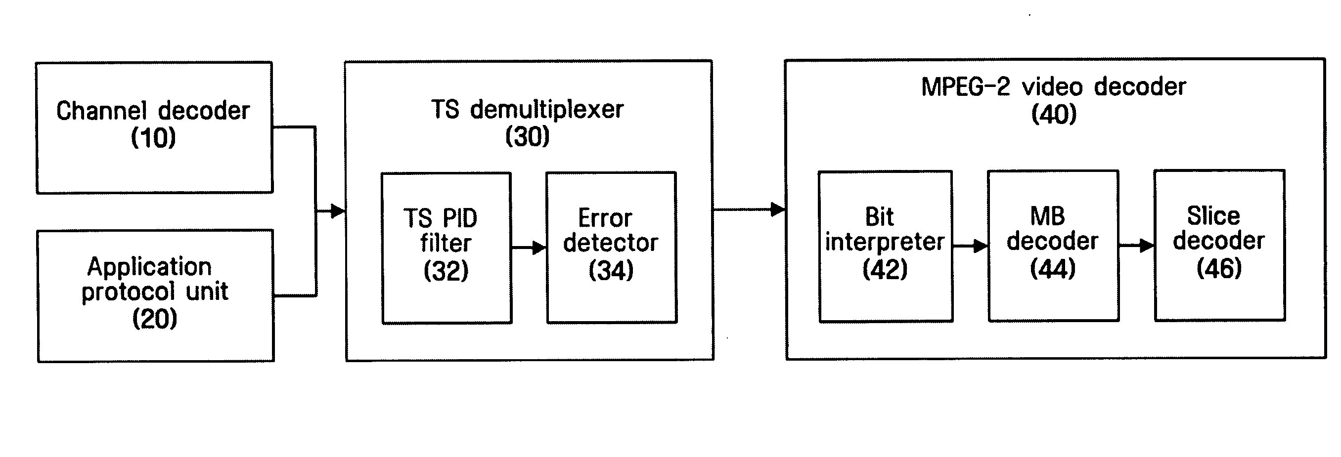
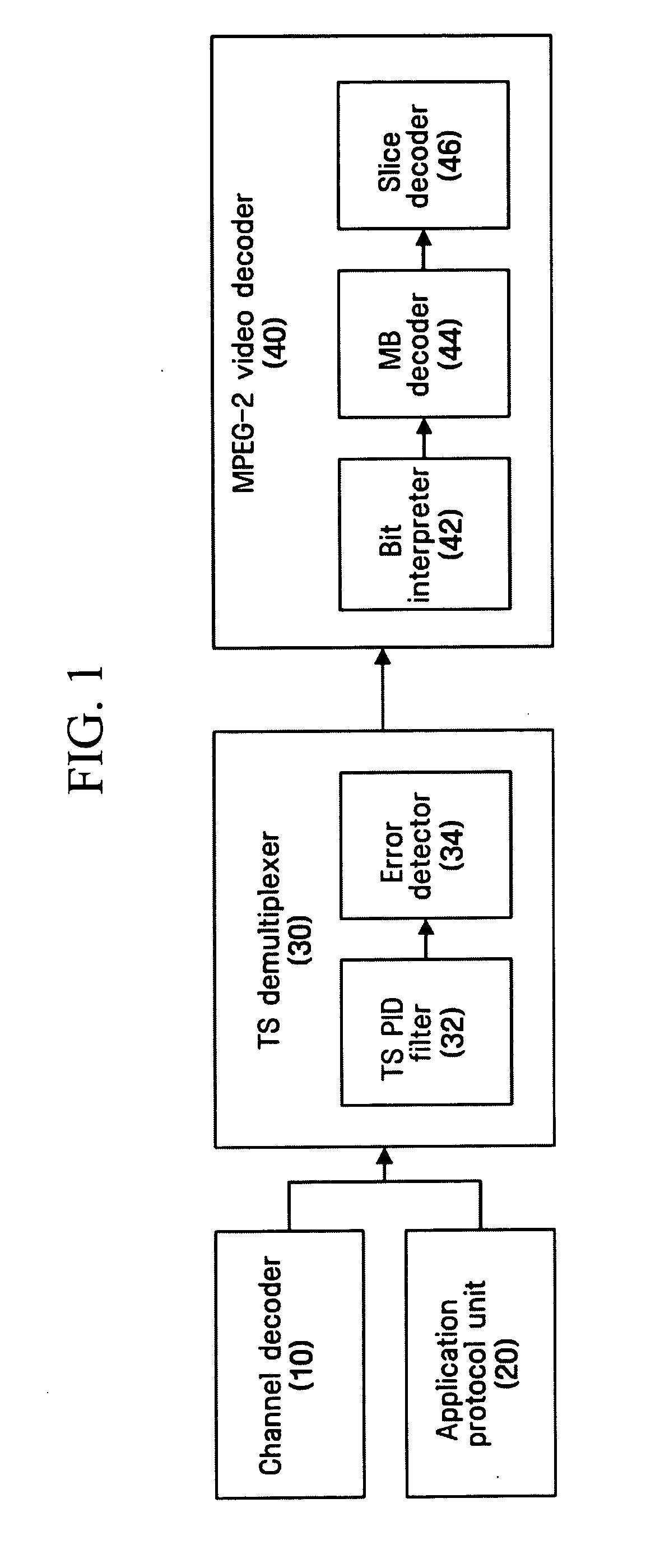
[0032] Referring to FIG. 1 showing the configuration of an MPEG-2 video decoding system, a digital TV broadcast signal is received through a channel decoder 10, and packets transmitted through a network such as the Internet is received through an application protocol unit 20. The video decoding system further includes a transport stream (TS) demultiplexer 30 that demultiplexes a broadcast signal (TS packets) received from a broadcasting signal receiver such as the channel decoder 10 or the application protocol unit 20 and extracts a video stream and an MPEG-2 video decoder that decompresses the video stream into a video signal.

[0033] The channel decoder 10 receives TS packets by performing RF demodulation on a broadcast signal on a channel selected by a user. Error detection is performed on the received TS packets using channel coding and Cyclic Redundancy Check (CRC). For a packet with an error, a Transport Error Indicator flag in a TS header is set to 1. Furthermore, in the case ...


PUM


Abstract

Provided are a method and apparatus for detecting an error during video decoding and handling of the error. An error is detected in a received video stream having a predetermined format, error information is recorded at a predetermined location of the video stream, and the type of the error is determined using the recorded error information. The video decoder includes a broadcast signal receiver that extracts a broadcast stream from a broadcast signal being transmitted via a transmission medium, a demultiplexing and error detection unit that demultiplexes the broadcast stream of a predetermined format extracted by the broadcast signal receiver for extraction of a video stream, detects errors in packets making up the extracted video stream, and records error information at a predetermined location of the video stream, and a video decoding unit that interprets the error information, determines the type of the errors using a predetermined method, and decodes the video stream according to the result of determination. The type and position of an error may be determined during video decoding. The video decoder is able to improve video quality by performing proper error concealment according to the type of error determined.

Description

CROSS-REFERENCE TO RELATED APPLICATION [0001] This application claims priority from Korean Patent Application No. 10-2003-0075646 filed on Oct. 28, 2003 in the Korean Intellectual Property Office, the disclosure of which is incorporated herein by reference in its entirety. BACKGROUND OF THE INVENTION [0002] 1. Field of the Invention [0003] The present invention relates to a method and apparatus for detecting and handling errors during a video decoding process in a video decoder. [0004] 2. Description of the Related Art [0005] With the development of information communication technology including the Internet, video communication as well as text and voice communication has increased. Conventional text communication cannot satisfy the various demands of users, and thus multimedia services that can provide various types of information such as text, pictures, and music have increased. Multimedia data requires a large capacity storage medium and a wide bandwidth for transmission since th...

Claims


Application Information

Patent Timeline
IPC IPC(8): H04N19/89H04N19/895
CPCH04N19/70H04N19/895H04N19/89H04N19/61
Inventor KIM, SUNG-JOO
Owner SAMSUNG ELECTRONICS CO LTD
Why Eureka
Try Eureka