Method for providing integrity measurements with their respective time stamps

a technology of integrity measurement and time stamp, applied in the field of information security, can solve the problems of not providing the actual moment of time, not providing the challenger with information about the time of integrity measurement, and personal computer users not being able to fully trust the operation of their computers

a technology of integrity measurement and time stamp, applied in the field of information security, can solve the problems of not providing the actual moment of time, not providing the challenger with information about the time of integrity measurement, and personal computer users not being able to fully trust the operation of their computers

US20060074600A1Inactive Publication Date: 2006-04-06INTEL CORP

Image

  • Method for providing integrity measurements with their respective time stamps
  • Method for providing integrity measurements with their respective time stamps
  • Method for providing integrity measurements with their respective time stamps

Examples


Embodiment Construction

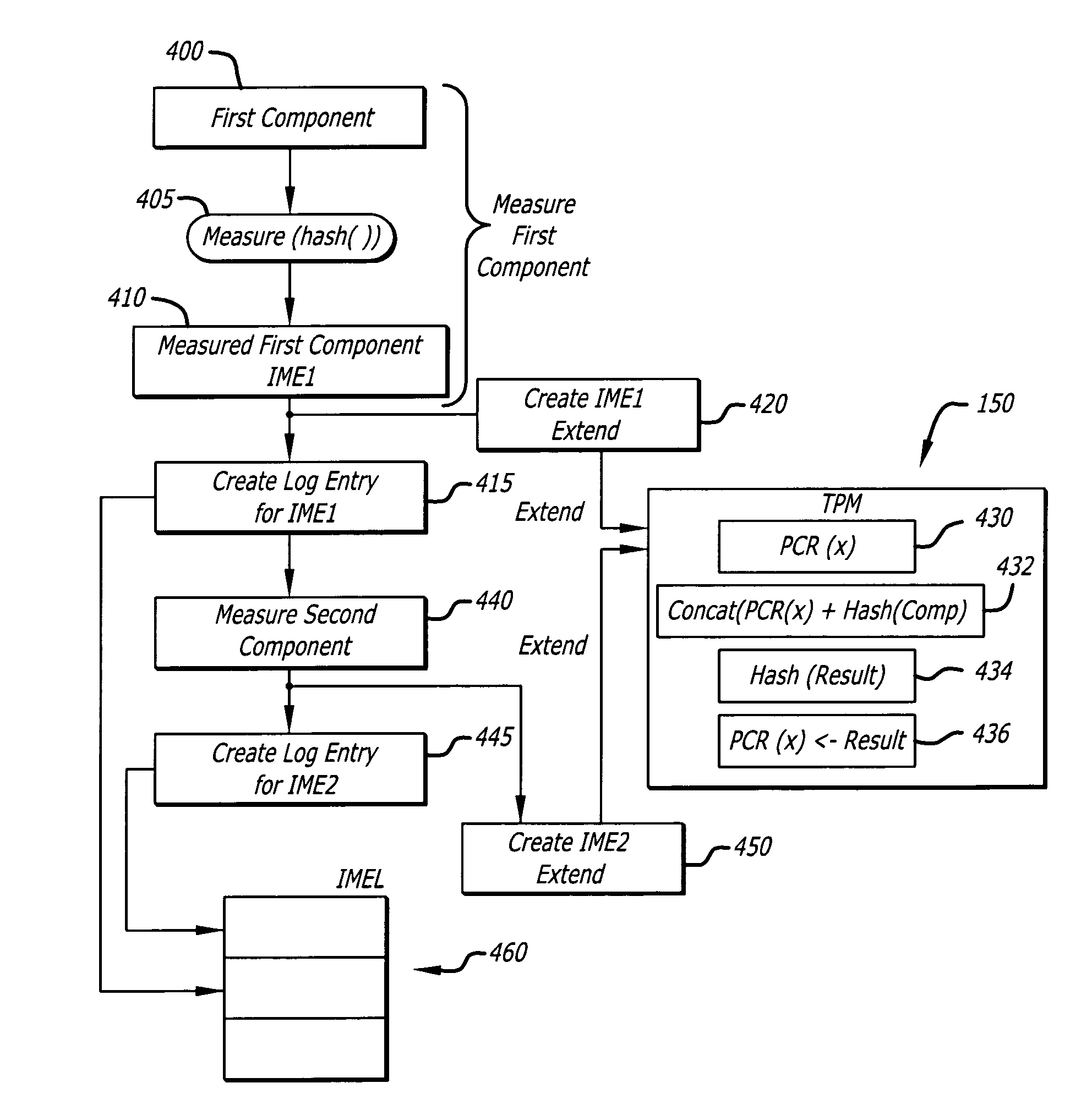
[0016] In general, various embodiments of the invention describe a method for associating integrity measurement events with actual time. More specifically, one embodiment of the invention pertains to the creation of an integrity time stamp based on an integrity measurement conducted on a component to indicate when the component was measured.

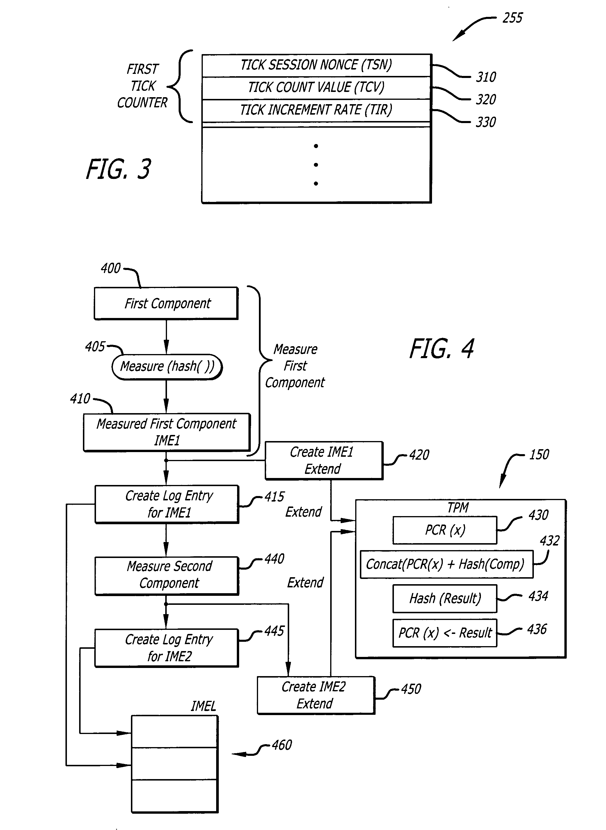
[0017] According to one embodiment of the invention, the integrity time stamp is produced based on the operations of a tick counter during a Trusted Platform Module (TPM) Transport Session (TTS). The tick counter is used to establish a chronological relationship between the beginning and end of an Integrity Metric Session (IMS) and the events (caused by the issuance of commands) within it. An “IMS” is a series of Integrity Measurement Events (IMEs) that are chronologically associated. Each IME is an integrity metric, namely a measured result obtained during an integrity measurement operation. According to one embodiment of the invention, the IME...


PUM


Abstract

According to one embodiment of the invention, a method comprises conducting a first integrity measurement to produce a first integrity measurement event. Thereafter, an integrity time stamp associated with the first integrity measurement event is created. The integrity time stamp is used to identify the actual time when the first integrity measurement event was produced.

Description

1. FIELD [0001] Embodiments of the invention generally relate to the field of information security. More specifically, embodiments of the invention relate to a method conducted within a trusted computing platform for associating integrity measurement events with actual time. 2. GENERAL BACKGROUND [0002] Over the last decade, the growing popularity of networks, namely a widespread connection of computing platforms, has greatly enhanced workforce productivity and influenced the daily activities for many individuals. Personal computers and other types of computing platforms are now considered invaluable business and communication tools. Therefore, with the growing number of viruses, trojan horses and other malicious code propagating over the networks, it is becoming increasingly important to protect the integrity of information within a computing platform. [0003] Many types of computing platforms, such as personal computers for example, are typically configured with an open, standard a...

Claims


Application Information

Patent Timeline
06 Apr 2006
Publication
US20060074600A1
IPC
G06F15/00
CPC
G06F21/57; G06F2221/2151
Inventors
SASTRY, MANOJ R.; WISEMAN, WILLARD M.