
Washing machine

a washing machine and drum technology, applied in the field of washing machines, can solve the problems that the drum b>6/b> mounted in the conventional washing machine cannot generate sufficient damping force, and achieve the effect of properly attenuating the vibration or impact transmitted from the drum and maximizing the damping for

Inactive Publication Date: 2006-04-13
LG ELECTRONICS INC
View PDF8 Cites 29 Cited by
  • Summary
  • Abstract
  • Description
  • Claims
  • Application Information

AI Technical Summary

Benefits of technology

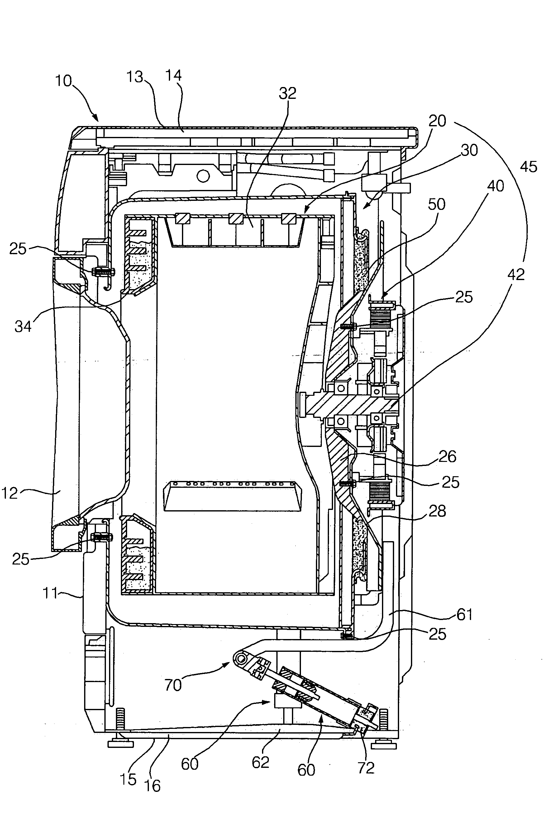
[0020] Therefore, the present invention has been made in view of the above problems, and it is an object of the present invention to provide a washing machine having dampers that are capable of effectively absorbing vibration and impact generate in several directions.
[0031] According to the present invention, multi-directional vibration or impact is absorbed by the cooperation of the bracket, the revolute joint connection unit, and the damper. Consequently, the present invention has the effect of more properly attenuating vibration or impact transmitted from the drum.
[0032] According to the present invention, the revolute joint connection unit is mounted in the washing machine. As a result, the damper is rotated about the joint pin, and therefore, the shock-absorbing operation is performed by the bushing, which is made of a resilient material, when multi-directional vibration or impact is transmitted to the damper. Consequently, the present invention has the effect of applying the damping force to the multi-directional vibration or impact.
[0033] According to the present invention, the shock-absorbing operation is performed by the resilient force of the bushing disposed at the outer circumferential surface of the lower part of the damper. Consequently, the present invention has the effect of maximizing the damping force in any directions.

Problems solved by technology

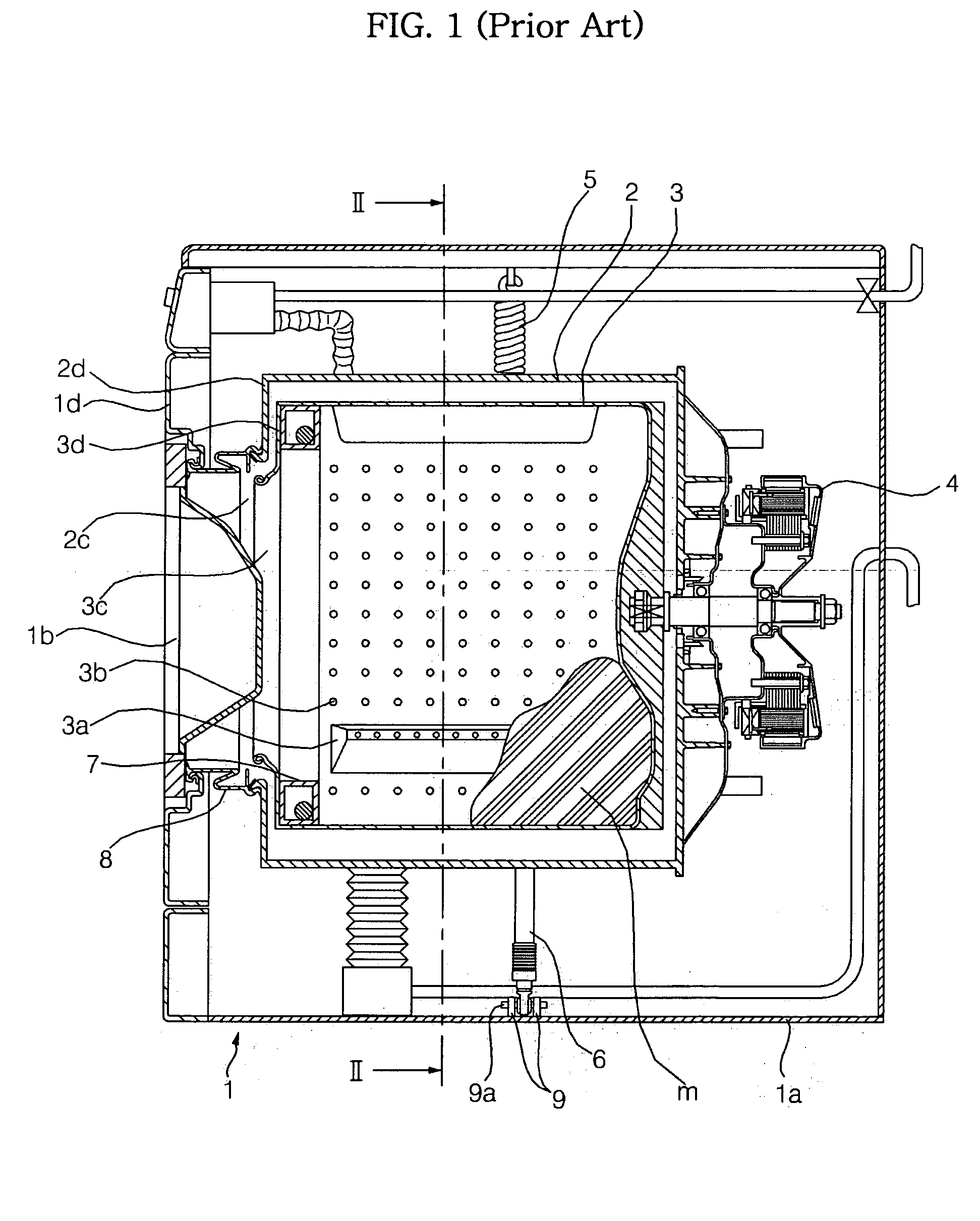
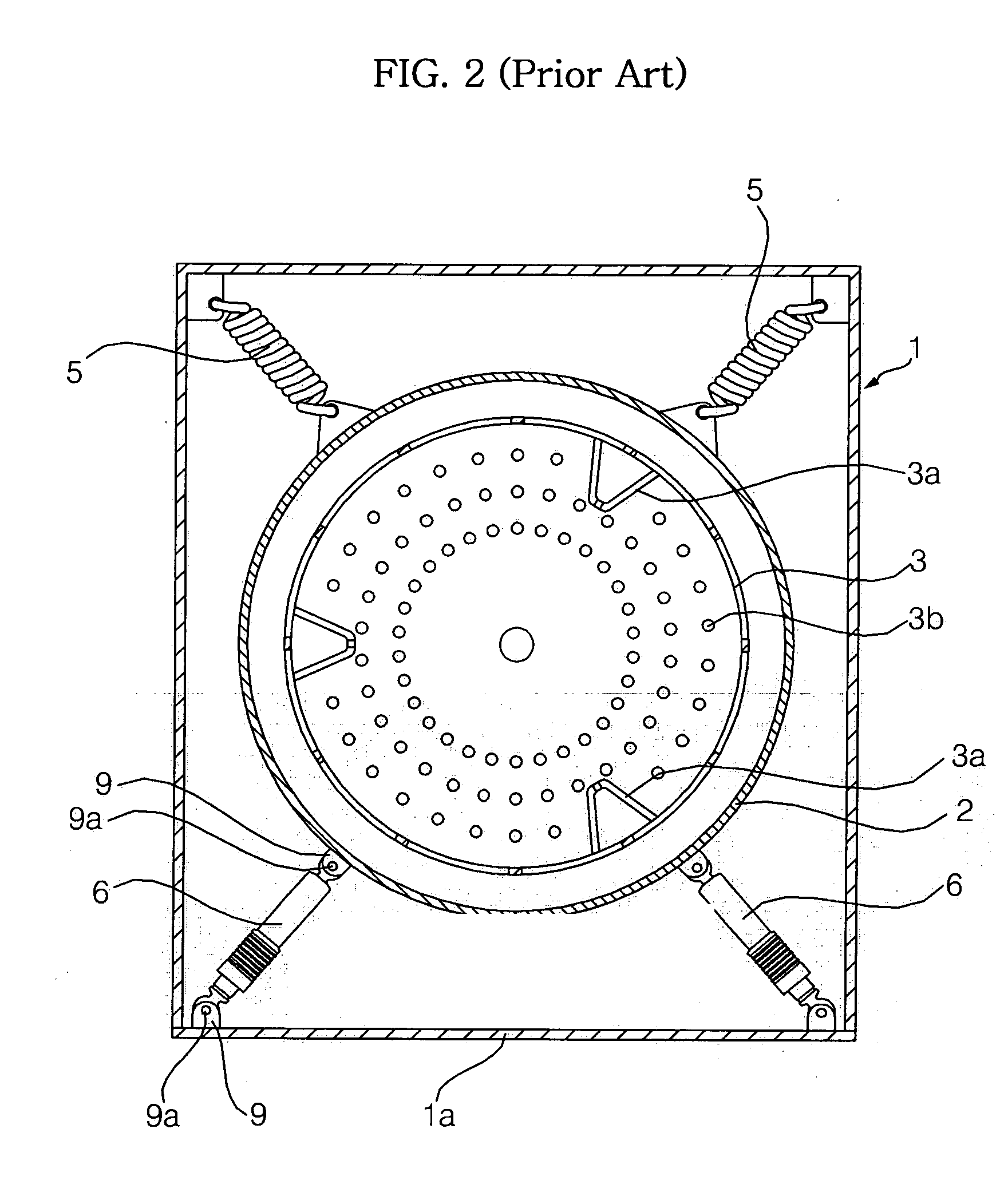
In conclusion, the dampers 6 mounted in the conventional washing machine cannot generate sufficient damping force.

Method used


Image

  • Washing machine
  • Washing machine
  • Washing machine

Examples


Embodiment Construction

[0043] Now, preferred embodiments of the present invention will be described in detail with reference to the accompanying drawings. In the drawings, the same or similar elements are denoted by the same reference numerals even though they are depicted in different drawings, and a detailed description thereof will not be given.

[0044]FIG. 4 is a sectional view illustrating the interior structure of a washing machine according to the present invention, FIG. 5 is an exploded perspective view illustrating a tub of the washing machine according to the present invention, FIG. 6 is a sectional view illustrating a damper of the washing machine according to the present invention, FIG. 7 is a view illustrating an example of the operation of the damper of the washing machine according to the present invention, and FIG. 8 is a view illustrating another example of the operation of the damper of the washing machine according to the present invention.

[0045] As shown in FIGS. 4 and 5, the washing m...


PUM


Abstract

Disclosed herein is a washing machine. The washing machine comprises at least one damper disposed between a drive part of the washing machine and a cabinet for performing shock-absorbing operation, a damper bracket fixedly attached to the drive part for transmitting vibration or impact to the at least one damper, and a revolute joint connection unit connected between the at least one damper and the damper bracket. When non-horizontal vibration or impact is transmitted to the at least one damper, the damper is rotated by the revolute joint connection unit. Consequently, the shock-absorbing operation is effectively performed.

Description

BACKGROUND OF THE INVENTION [0001] 1. Field of the Invention [0002] The present invention relates to a washing machine, and, more particularly, to a washing machine having dampers each of which has one end connected to one side of a drum in a revolute joint fashion for effectively absorbing vibration generated from a driving part of the washing machine. [0003] 2. Description of the Related Art [0004]FIG. 1 is a sectional view illustrating the interior structure of a conventional drum type washing machine, FIG. 2 is a sectional view taken along line II-II of FIG. 1, and FIG. 3 is a sectional view illustrating the interior structure of the damper shown in FIG. 1. [0005] As shown in FIGS. 1 and 2, the conventional drum type washing machine comprises: a cabinet 1 having a base 1a and a door 1b; a tub 2 fixedly mounted in the cabinet 1; a drum 3 rotatably mounted in the tub 2 such that laundry m and washing water are shaken by lifters 3a; a motor 4 for rotating the drum 3; and springs 5,...

Claims


Application Information

Patent Timeline
IPC IPC(8): D06F37/22
CPCD06F37/22F16F7/09F16F15/022D06F39/125Y02B40/00
Inventor SEO, HYUN SEOKLIM, HEE TAE
Owner LG ELECTRONICS INC
Learn More