Path setting method, and network, relay station and parent station employing the path setting method

a relay station and path setting technology, applied in data switching networks, power distribution line transmission, high-level techniques, etc., can solve the problems of difficult to design a network in a desktop manner, power-line communication has been required to take a great deal of manual effort and time, and excellent communication cannot always be maintained

Inactive Publication Date: 2006-04-13
THE KANSAI ELECTRIC POWER CO +1
View PDF4 Cites 193 Cited by
  • Summary
  • Abstract
  • Description
  • Claims
  • Application Information

AI Technical Summary

Benefits of technology

[0017] In the path setting method, the network, the relay station and the parent station according to the present invention, each of the parent station and the plurality of relay stations transmits the basic-information notification signal containing the basic information by means of a broadcast, and each of the relay stations receives the basic-information notification signals from other stations, so that each of the relay stations recognizes the parent station or the relay station having a temporary path set thereto. Then, each of the relay stations transmits the receiving-environment-table communication signal to the recognized parent station or the recognized relay station having the temporary path. When the recognized relay station receives the receiving-environment-table communication signal, it forwards the receiving-environment-table communication signal to the parent station through the use of the temporary path. In this manner, the receiving-environment table of each of the relay stations is notified to the parent station. Then, the parent station sets a temporary path to the relay station which has transmitted the receiving-environment-table communication signal. Thus, according to the path setting method of the present invention, the parent station can set a temporary path stepwise to each of the relay stations in order of the closest relay station to the farthest relay station in terms of network topology. With the use of this temporary path, the parent station can collect from each of the relay stations the transmission qualities on inter-station transmission lines required for setting paths, so as to allow the parent station to automatically set the paths.

Problems solved by technology

This causes difficulties in designing a network in a desktop manner, because the layout position of a relay station cannot be pre-specified in developing the network.
Due to these situations, the power-line communication has been required to take a great deal of manual effort and time for the network development and the path setting operation.
Thus, even if a path is adequately set up, an excellent communication cannot be always maintained.

Method used


Image

  • Path setting method, and network, relay station and parent station employing the path setting method
  • Path setting method, and network, relay station and parent station employing the path setting method
  • Path setting method, and network, relay station and parent station employing the path setting method

Examples


embodiment

Operation of Embodiment

[0062]FIG. 5 is a flowchart showing an operation of transmitting basic information in each of the relay stations. FIG. 6 is a flowchart showing an operation of transmitting basic information in the parent station. FIG. 7 is a flowchart showing an operation of creating, updating and transmitting a receiving-environment table. FIG. 8 is a flowchart showing an operation of setting a temporary path. FIG. 9 is a flowchart showing an operation of setting a fixed-path.

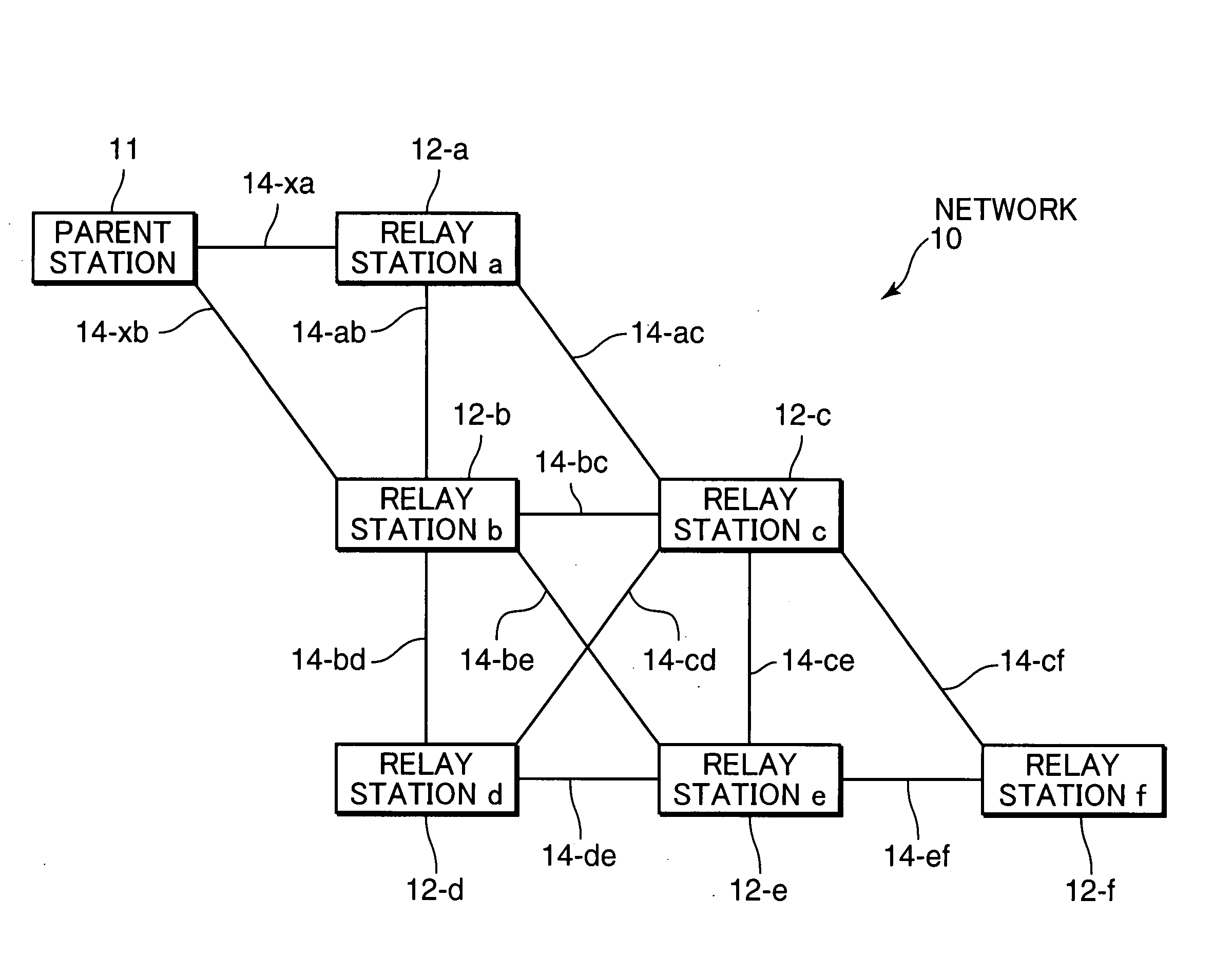
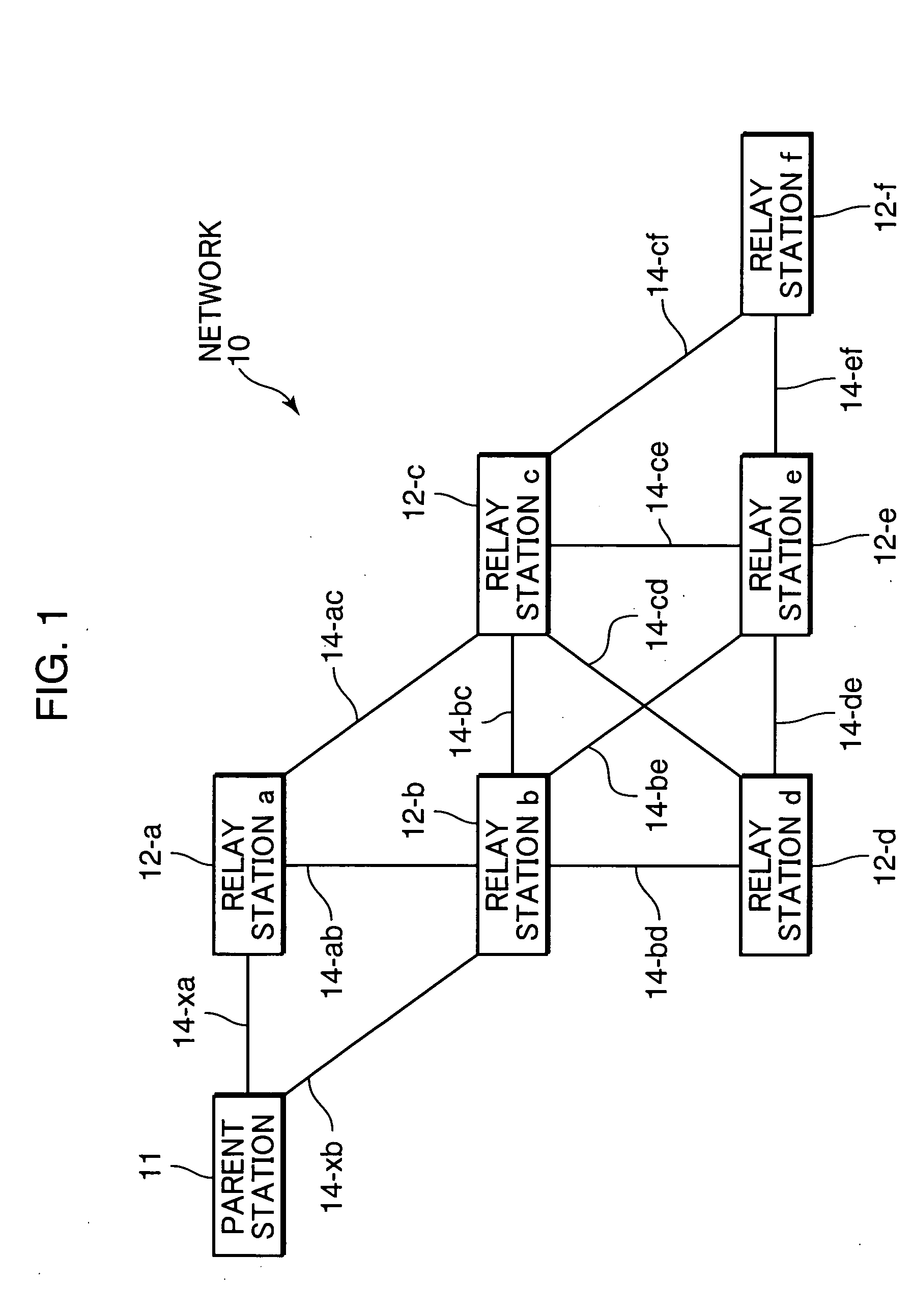
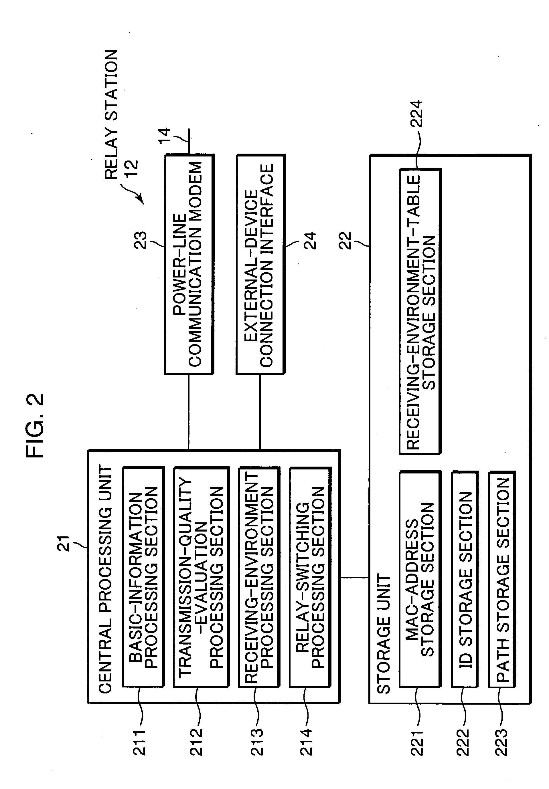
[0063] Firstly, an operation of transmitting basic information to notify the presence of its own station to other stations will be described. A developer or the like who intends to develop the network 10 firstly sets a network ID to each of the parent station 11 and the relay stations 12. For example, this setting operation is performed by connecting a setting device to each of the parent station 11 and the relay stations 12 through the external-device connection interface 34, 24, and inputting the net...


PUM


Abstract

The present invention provides a path setting method for automatically setting network paths. The path setting method for generating paths in a network including a plurality of relay stations and a parent station which are connected with each other through a transmission line, comprises the steps of allowing each of the parent station and the plurality of relay stations to transmit basic information including its own identifier and its own path setting status, by means of a repetitive broadcast, allowing the relay station receiving the basic information to recognize the parent station or another relay station having a temporary path set thereto and transmit its own receiving-environment table including a transmission quality on the transmission line to the recognized station, allowing the another relay station receiving the receiving-environment table to forward it to the parent station through the use of the temporary path so as to notify the receiving-environment table to the parent station, and allowing the parent station receiving the forwarded receiving-environment table to set a temporary path to the relay station which has transmitted the receiving-environment table. In this manner, the parent station collects the transmission qualities on the inter-station transmission lines stepwise in order of the closest relay station to the farthest relay station to automatically set the paths.

Description

TECHNICAL FIELD [0001] The present invention relates to a path setting method for automatically setting a path (communication path) from a parent station to a relay station or a child station in a network. The present invention also relates to a network, relay station and parent station employing the path setting method. BACKGROUND ART [0002] In order to transmit and receive communication signals between the respective nodes of a base or parent station, a relay station and a child station in a network, it is required to set a path according to the type of network, the transmission quality on a transmission line interconnecting between the nodes, and other factor. [0003] Late years, in connection with the progress of communication technologies, developments in networking have been made in various technical fields, and various devices in a house or building are increasingly being connected to networks. The device networking is intended to operate these devices in an organically linked...

Claims


Application Information

Patent Timeline
Patent Type & Authority Applications(United States)
IPC IPC(8): H04L12/28H04L12/46H04L45/02
CPCH04B3/58H04B2203/5479H04L29/06H04L45/02H04L45/16H04W40/02H04L67/14Y02D30/70H04L9/40
Inventor MAEGAWA, KOJISAKAI, HIDEKIYAMAMOTO, SHINJI
Owner THE KANSAI ELECTRIC POWER CO
Why Eureka
Try Eureka