Radio communication system, radio communication apparatus, radio communication method, and computer program

a radio communication system and radio communication technology, applied in the field of radio communication systems, can solve the problems of difficult to readily construct a network, messy cabling, limited movement range of equipment,

Active Publication Date: 2006-07-27
REDWOOD TECHNOLOGIES LLC
View PDF8 Cites 61 Cited by
  • Summary
  • Abstract
  • Description
  • Claims
  • Application Information

AI Technical Summary

Benefits of technology

[0065] In a communication environment in which a plurality of ad-hoc networks are adjacent to each other, the present invention can provide a superior wireless communication system, a wireless communication apparatus, a wireless communication method, and a computer program which can preferably form an appropriate wireless network without communication terminals interfering with each other across the networks.
[0066] In a communication environment in which a plurality of ad-hoc networks are adjacent to each other, the present invention can provide a superior wireless communication system, a wireless communication apparatus, a wireless communication method, and a computer program which can preferably form a wireless network with a low-load network management configuration.
[0067] According to the present invention, in a wireless communication system in which a system timer and a master station that controls common frame time do not exist in a domain included in the system, each communication station, at least, periodically transmits / receives a beacon at regular intervals, and manages the transmission / reception using a neighboring-station list (a neighbor list). This makes it possible to manage the network of the communications station in a distributed manner. In addition, a mechanism for managing n beacons (n is an integer greater than or equal to one) transmitted / received at regular time intervals, using a neighboring-station list, is provided and a save area for receiving a number of beacons which is greater than n at the regular time intervals is provided. As a result, there is an advantage in that hardware (during reception of a new beacon) and the software (during update of the list) can easily schedule the list reading / writing processing to thereby prevent occurrence of a failure in the neighboring-station list. Further, this arrangement makes it possible to perform operation without a failure, even when a high-load situation for managing the network, such as a situation in which network topologies are crossed over, arises.

Problems solved by technology

In such a case, however, line installation work is required, which makes it difficult to readily construct a network.
In addition, the cabling is messy.
After the LAN is constructed, the movement range of equipment is limited by the cable length, which is inconvenient.
Thus, there is a problem in that the use efficiency of the transmission path is reduced by half.
The first problem is collision due to a change in the radio-wave propagation environment.
However, in an environment such as a home network where the user gets across between communication stations or the radio-wave propagation environment frequently changes, it is impossible to overcome issues, such as the issue of selecting, as the AP, a communication station located at which position and the issue of how to re-constitute the network when the AP is powered off.
Thus, it can be assumed that it is preferable to be able to construct a network without any coordinator, but such a demand cannot be met in the IEEE 802.11 infrastructure mode.
The second problem is collision resulting from a network environment change due to a mobile terminal.
Although it is desired that a network can be constructed without a need for a coordinator (as described above), such a demand cannot be met in the IEEE 802.11 infrastructure mode.
The third problem is a configuration for managing a network in which the loads of communications are low.
However, as the number of neighboring stations that each neighboring station can handle increases, the load of each neighboring station increases.
This can lead to a load on the entire network.

Method used


Image

  • Radio communication system, radio communication apparatus, radio communication method, and computer program
  • Radio communication system, radio communication apparatus, radio communication method, and computer program
  • Radio communication system, radio communication apparatus, radio communication method, and computer program

Examples


first embodiment

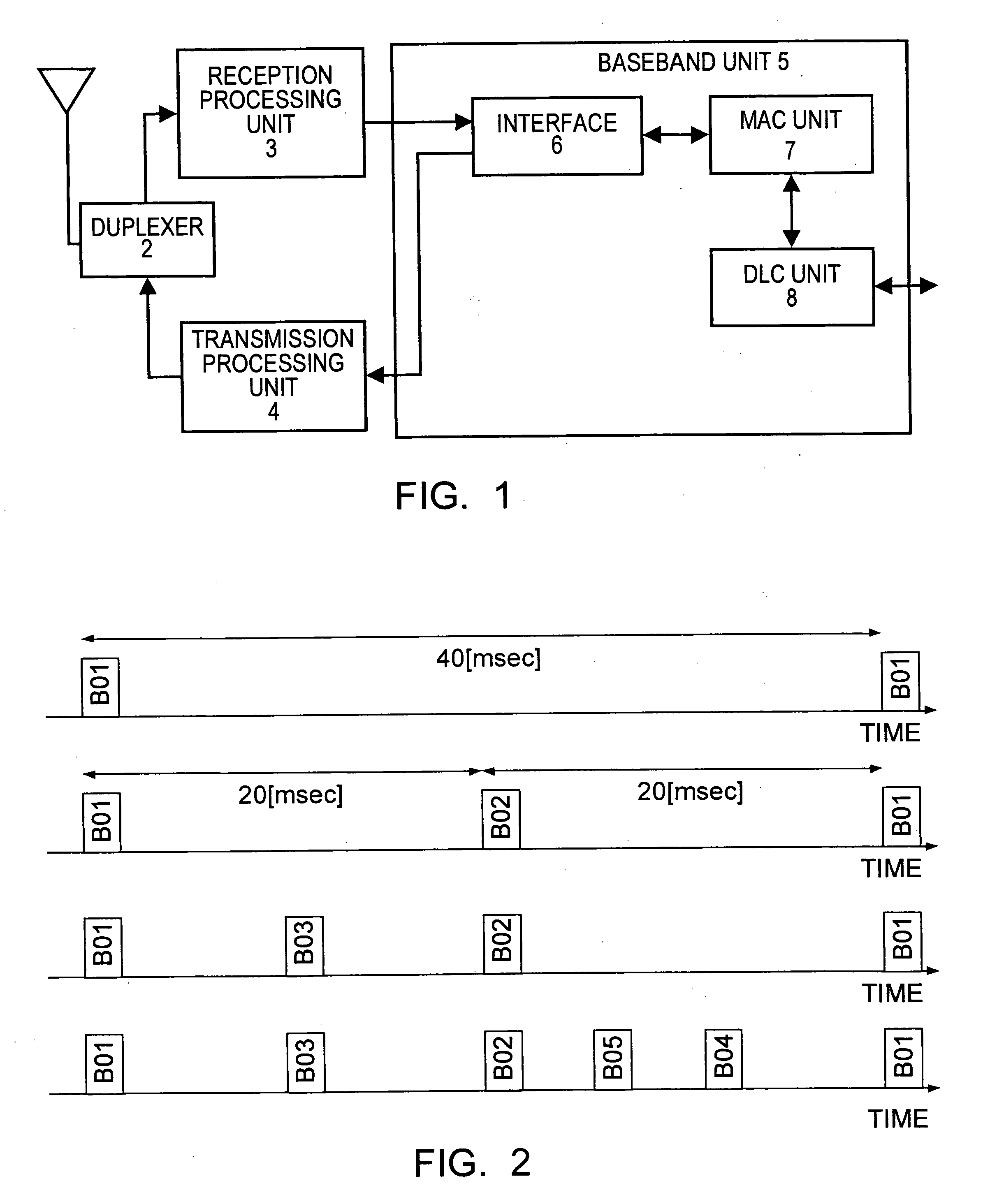
[0074]FIG. 1 schematically shows the functional configuration of a wireless communication apparatus that is capable of operating as a communication station in a wireless network according to the present invention.

[0075] In the wireless communication apparatus shown in the figure, an antenna 1 is connected to a reception processing unit 3 and a transmission processing unit 4 via an antenna duplexer 2. The reception processing unit 3 and the transmission processing unit 4 are connected to a baseband unit 5. Various communication systems that are applicable to, for example, a wireless LAN and that are suitable for relatively short-distance communication can be used for the reception processing system of the reception processing unit 3 and the reception processing system of the transmission processing unit 4. Specifically, a UWB system, an OFDM system, or a CDMA system can be used.

[0076] The baseband unit 5 includes an interface unit 6, a MAC (media access control) unit 7, a DLC (data...

second embodiment

[0137] In a network in which a coordinator is not required, the neighboring-station list is considered to be a network-control core that controls the synchronization with each communication station to enable data communication between communication stations. Correspondingly, hardware (or a communication-protocol lower layer) or software (or a communication-protocol higher layer) is required to execute complicated control, such as transmission / reception scheduling, via the neighboring-station list. Thus, for incorporation into each communication station, it s desired that the neighboring-station list has a structure that allows for more simplified control.

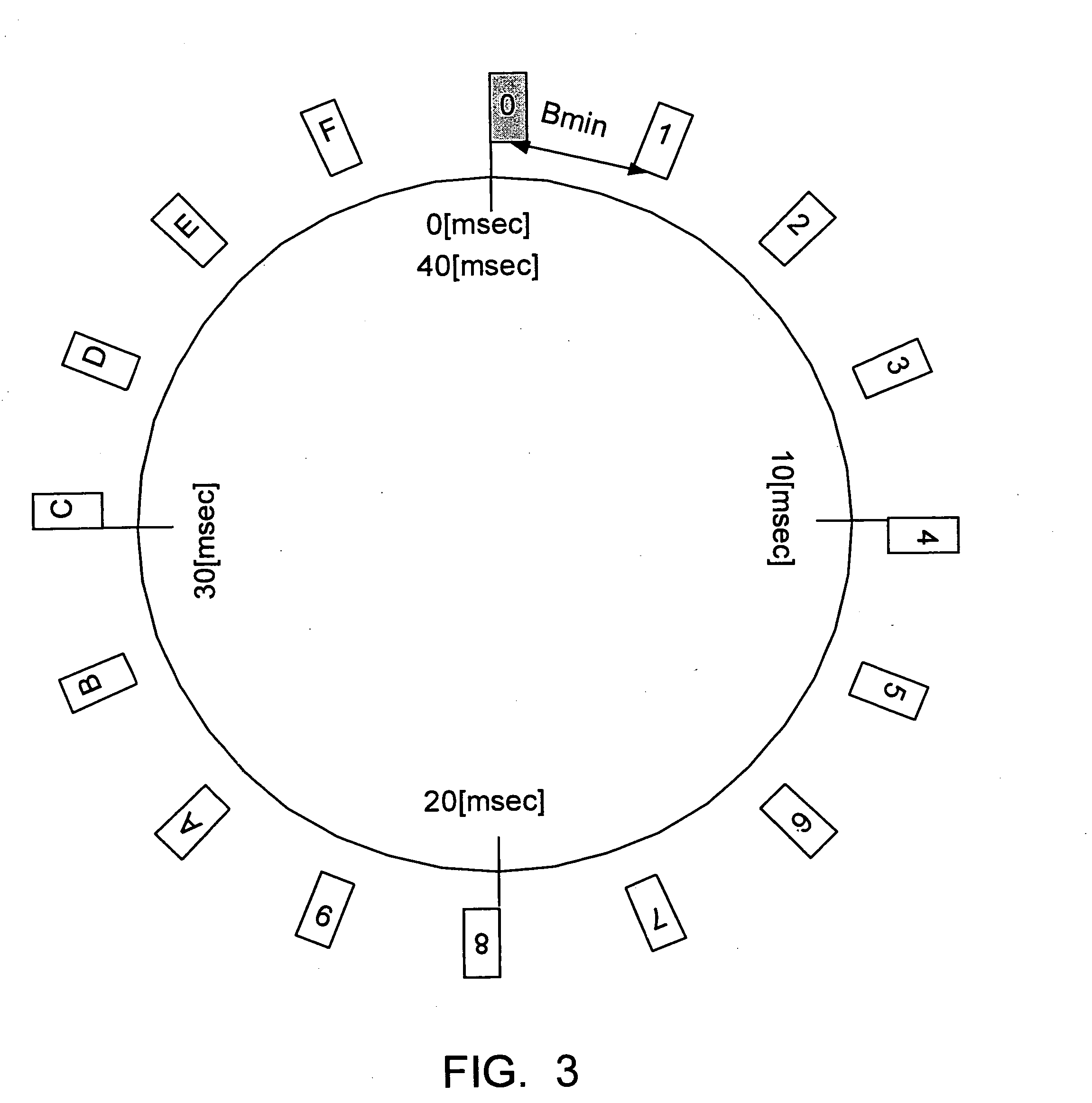
[0138] The structure of the neighboring-station list that allows the hardware and / or software to achieve more simplified control will be described in the present embodiment. In the present embodiment, a system in which the beacon transmission timing of the self station is 40 microseconds and the minimum interval Bmin of beacons rec...

third embodiment

[0150] In the present embodiment, in a network in which no coordinator is required, a system in which the beacon transmission timing of the self station is 40 microseconds and the minimum interval Bmin of beacons received from other communication stations is 625 microseconds is considered, as in the second embodiment. In this case, the beacons of 64 stations(=40 / 0.625) can be incorporated to configure a network including the self station. A neighboring-station list for a system having a maximum number of 64 stations will be described below. The present embodiment can further ensure the operation of scheduling for reading / writing performed by the hardware (or a communication-protocol lower layer that writes a newly obtained beacon in the save area) and the software (or a communication-protocol upper layer that relocates the beacon in the save area to the ordinary area).

[0151]FIG. 20 shows the structure of a neighboring-station list in the present embodiment. In the example shown in ...


PUM


Abstract

Each communication station, at least, periodically transmits/receives a beacon at regular intervals and manages the transmission/reception using a neighboring-station list (neighbor list), thereby managing the network of the communications station in a distributed manner. In addition, a save area is provided in which n beacons transmitted/received at regular time intervals are managed in a neighboring-station list, thereby making it easy to schedule list reading/writing processing when the list is updated during the reception of a new beacon. When the network topologies are crossed over, a load for network management can be reduced. Thus, it is possible to provide a wireless communication system in which a system timer and a master station that controls common frame time do not exist in a domain included in the system.

Description

TECHNICAL FIELD [0001] The present invention relates to wireless communication systems, wireless communication apparatuses, wireless communication methods, and computer programs which mutually perform communication between a plurality of wireless communication stations in a wireless LAN (Local Area Network) or the like. In particular, the present invention relates to a wireless communication system, a wireless communication apparatus, a wireless communication method, and a computer program for operation of a wireless network through asynchronous direct communication (random access) of terminal apparatuses. [0002] More specifically, the present invention relates to wireless communication systems, wireless communication apparatuses, wireless communication methods, and computer programs for construction of a wireless network through ad-hoc (ad-hoc) communication without the relationship of a controlling station and a controlled station. In particular, the present invention relates to a...

Claims


Application Information

Patent Timeline
Patent Type & Authority Applications(United States)
IPC IPC(8): H04L12/413H04J3/08H04J3/06H04B7/14H04J1/10H04W48/10H04W56/00H04W72/04H04W72/06H04W74/08H04W84/12H04W84/18
CPCH04W24/00H04W28/06H04W48/08H04W48/16H04W56/0045H04W84/18H04W74/08
Inventor IWAMI, HIDEKISAKODA, KAZUYUKIYAMAGATA, TOMONARI
Owner REDWOOD TECHNOLOGIES LLC
Why Eureka
Try Eureka