Earphone connector assembly

Inactive Publication Date: 2006-04-20
YANG JOHNSON
View PDF5 Cites 9 Cited by
  • Summary
  • Abstract
  • Description
  • Claims
  • Application Information

AI Technical Summary

Benefits of technology

[0010] The primary object of the present invention is to provide an earphone connector assembly which comprises: a connector, a cover and a plurality of independent terminals. The connector is provided with a plurality of sockets, in the sockets are formed a plurality of retaining holes, and the independent terminals are provided with non-return flap in response to the sockets. With the help of the non-return flap and the retaining hole, the independent terminal can be quickly and easily fixed in the sockets of the connector. Thereby, the earphone connector of the present invention can be easily assembled and the cost is accordingly decreased.

Problems solved by technology

In this cost, the assembling cost for the conventional earphone connector is high, and the assembling rate is accordingly slow.

Method used


Image

  • Earphone connector assembly
  • Earphone connector assembly
  • Earphone connector assembly

Examples


Embodiment Construction

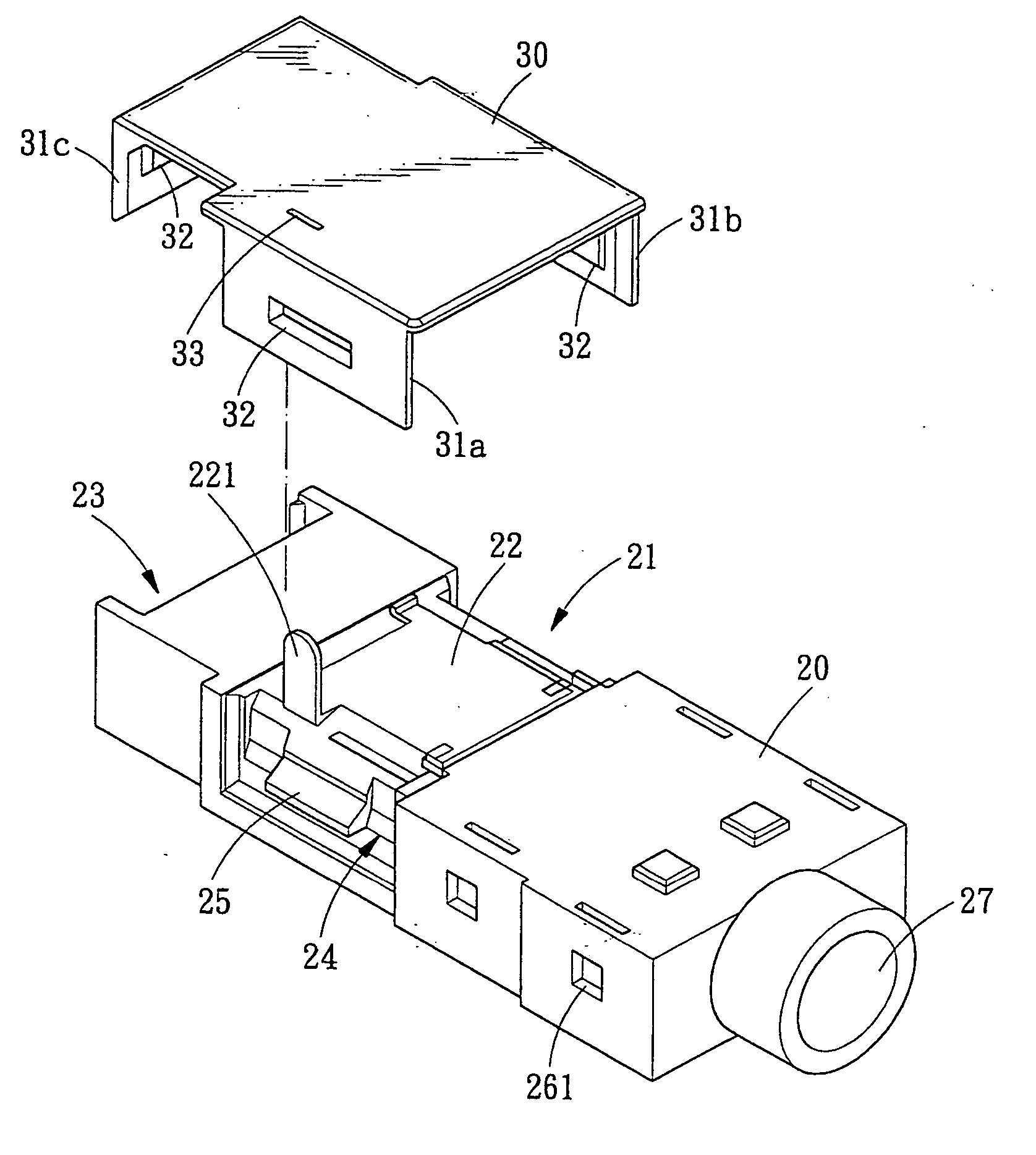
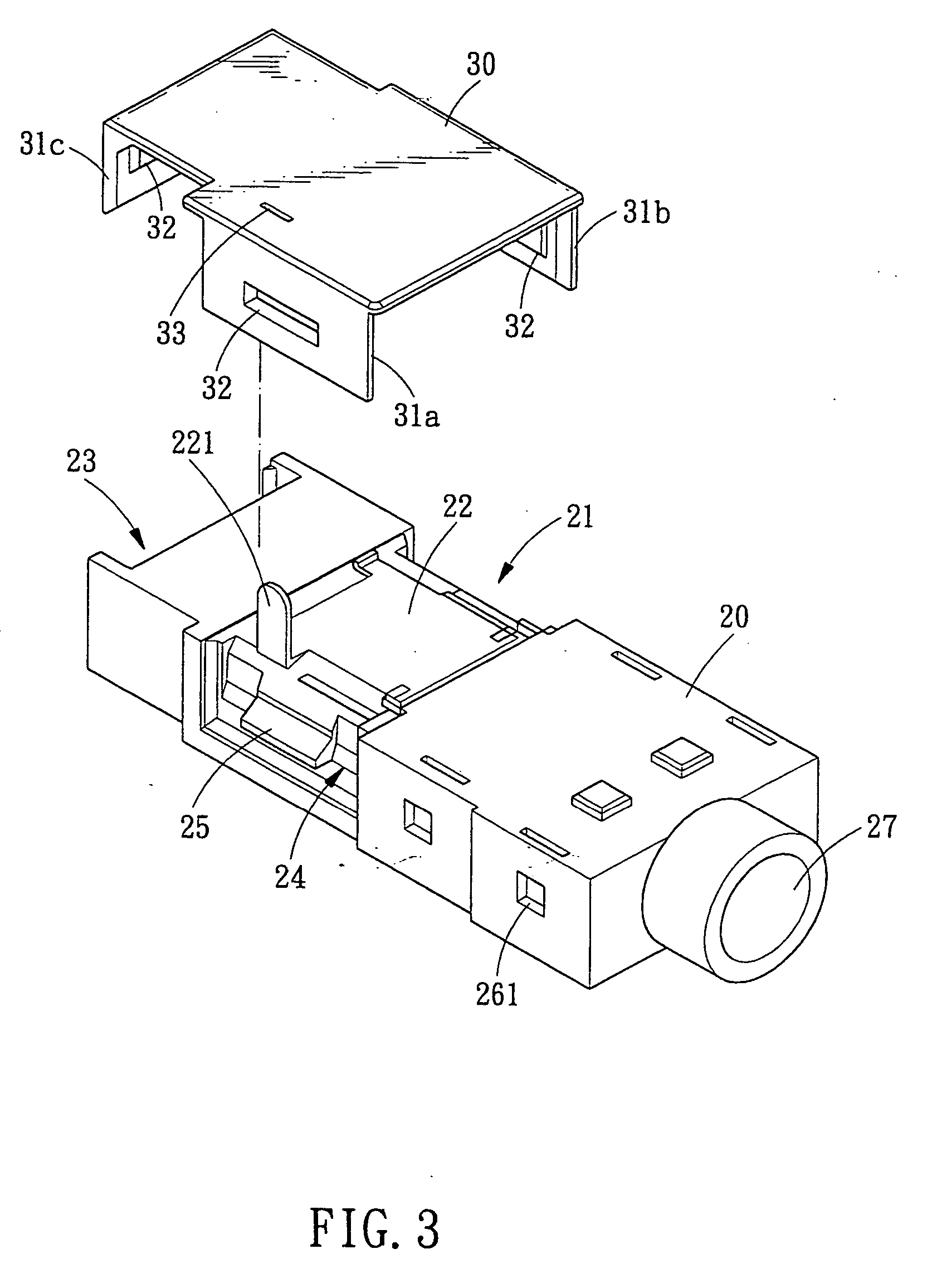
[0020] Referring to FIGS. 3-6, an earphone connector assembly in accordance with the present invention generally comprises: a connector 20, a cover 30 and a plurality of independent terminals 40.

[0021] The connector 20 is an integral member made of plastic material and formed with a “Π” shaped recess 21. In the “Π” shaped gap 21 is provided a metal terminal 22 which has a folded metal end 221, at a terminal end of the connector 20 is formed a gap 23. At both sides of the recess 21 is defined a concaved side 24 which is provided with a locking projection 25. In the gap 23 is also provided a locking projection 25. A plurality of sockets 26 are formed on the surface of the connector 20, and the opening direction of the sockets 26 is opposite to the installation direction of the connector 20. The sockets 26 correspond to the connecting elements inside the connector 20. On the sidewall of the connector 20 are formed a plurality of rectangular retaining holes 261 which are in communicati...


PUM


Abstract

The present invention relates to an earphone connector assembly which comprises: a connector, a cover and a plurality of independent terminals. The connector is provided with a plurality of sockets, in the sockets are formed retaining holes, and the independent terminals are provided with non-return flap in response to the sockets. With the help of the non-return flap and the retaining hole, the independent terminal can be quickly and easily fixed in the sockets of the connector. Thereby, the earphone connector of the present invention can be easily assembled and the cost is accordingly decreased.

Description

BACKGROUND OF THE INVENTION [0001] 1. Field of the Invention [0002] The present invention relates to a connector, and more particularly to an earphone connector assembly. [0003] 2. Description of the Prior Arts [0004] Referring to FIG. 1, which is a cross sectional view of a conventional earphone plug, a jack 11 is formed at an end of the connector 10. In the connector 10 are disposed two folded terminals 12. One of the folded terminals 12 has a folded movable end 121 which serves to actuate a switch 13. A conductive element 14 is disposed in the switch 13 and slides on the metal terminals 15a, 15b, and 15c of the connector 10 along with the movement of the switch 13. [0005] Referring to FIG. 2, which is an operational view of a conventional earphone plug. When the user inserts an earphone plug 16 in the jack 11 of the connector 10, the earphone plug 16 will press the movable end 121 of the terminal 12, and the switch 13 will be caused to move. As a result, the conductive element 14...

Claims


Application Information

Patent Timeline
IPC IPC(8): H04R25/00
CPCH01R13/447H01R13/506H01R24/58H01R2103/00H04R1/10H04R1/1033
Inventor YANG, JOHNSON
Owner YANG JOHNSON
Why Eureka
Try Eureka