

Fly-by-wire limp home and multi-plex system
a technology of multi-plex system and fly-by-wire, which is applied in the direction of mechanical equipment, transportation and packaging, and gearing, etc., can solve the problem of not providing skip shifting
- Summary
- Abstract
- Description
- Claims
- Application Information
AI Technical Summary
Benefits of technology
Problems solved by technology
Method used
Image

Examples
Embodiment Construction
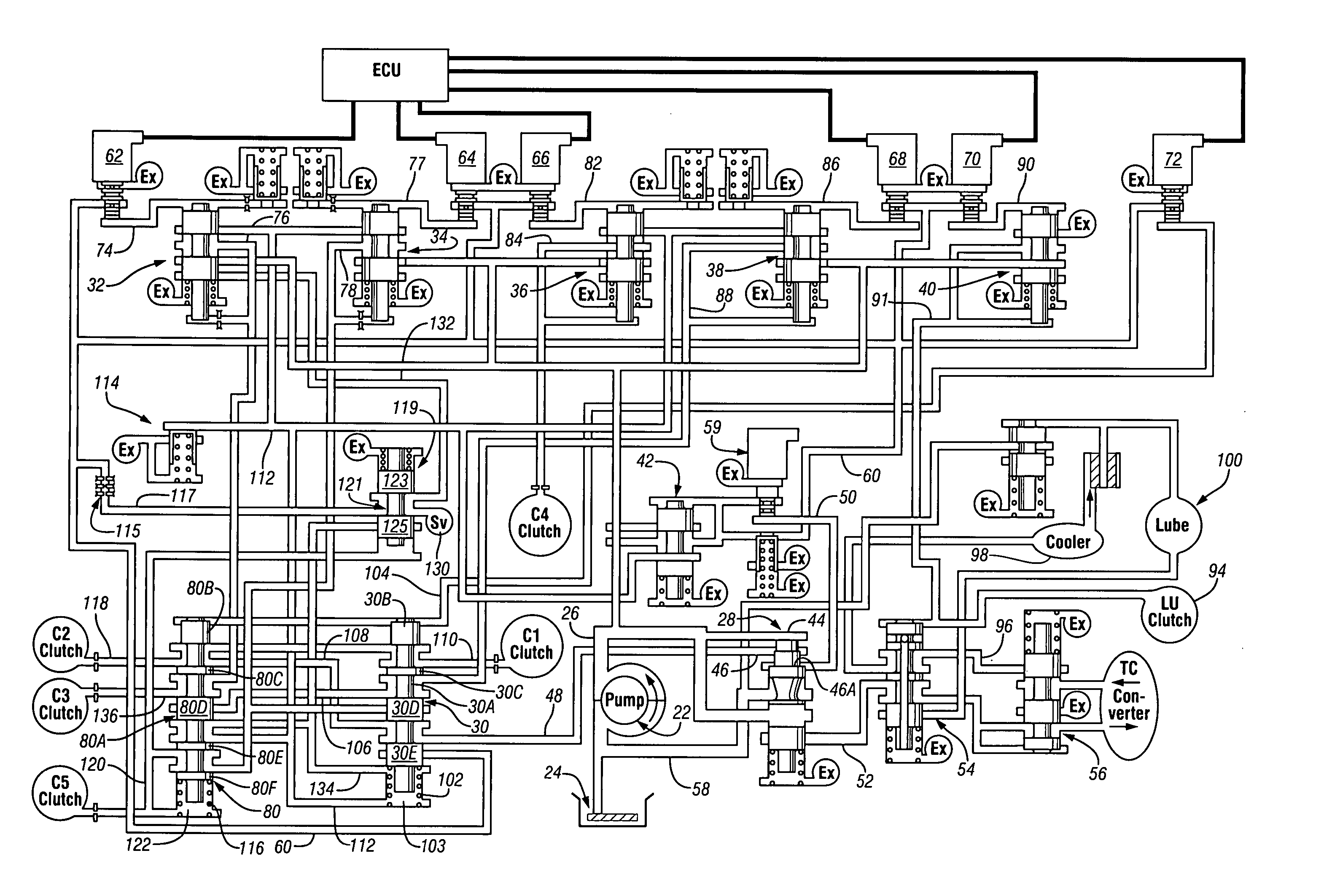
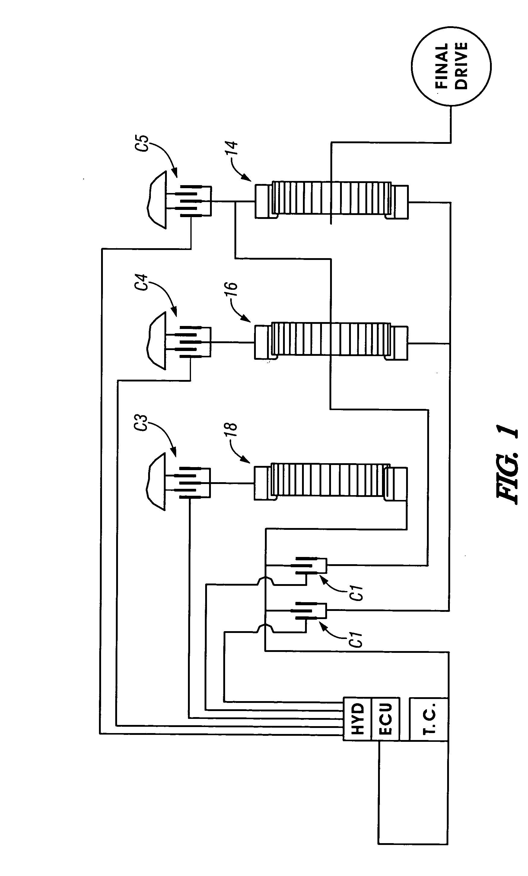
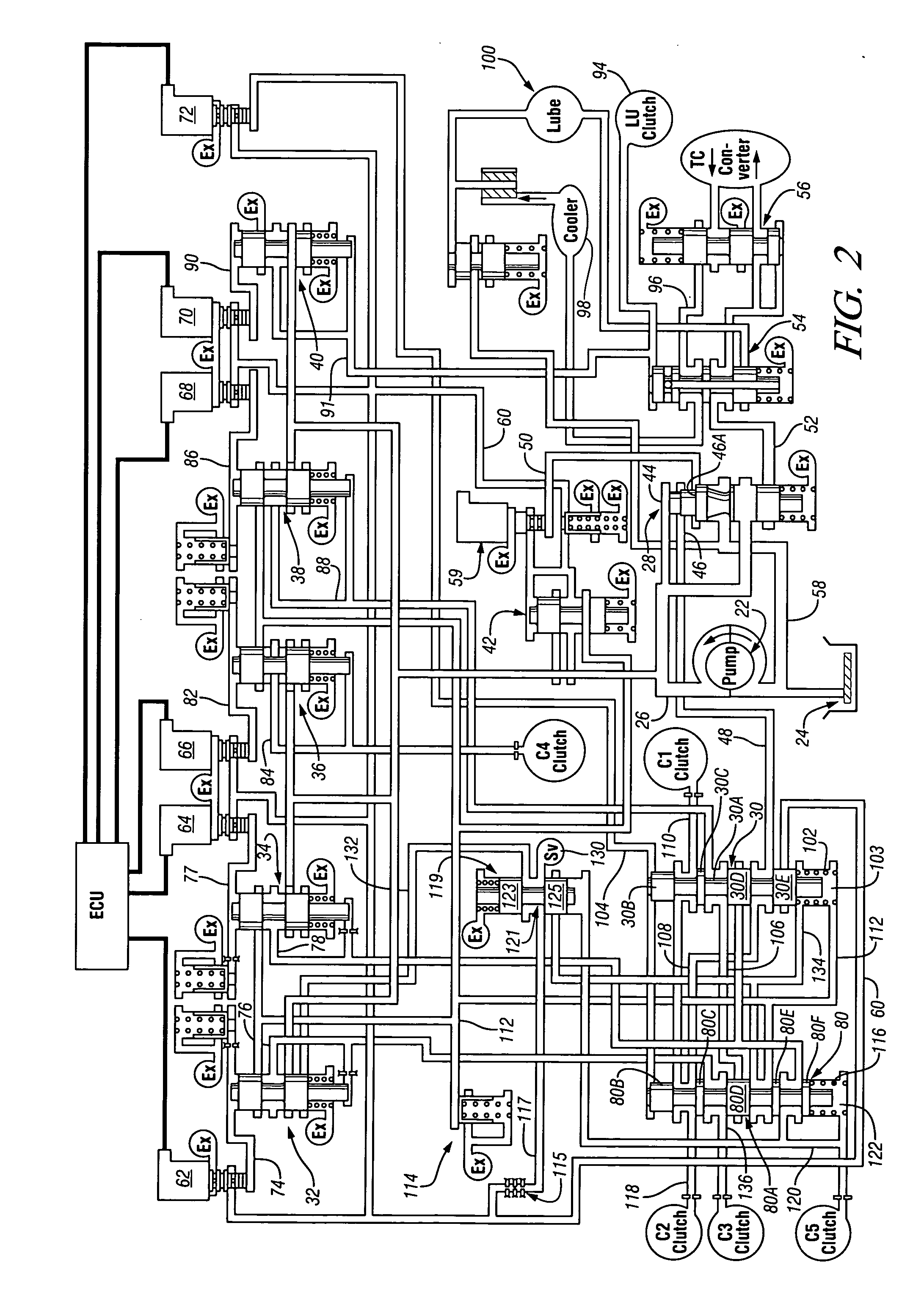
[0022] A power transmission shown in FIG. 1 includes an engine and torque converter (TC), an input shaft 10, an output shaft 12, and three planetary gearsets 14, 16, and 18. The planetary gearsets 14, 16, and 18 are controlled to provide six forward speed ratios, a reverse speed ratio, and a neutral condition between the input shaft 10 and the output shaft 12. These conditions are provided by five torque-transmitting mechanisms C1, C2, C3, C4, and C5. The torque-transmitting mechanisms C1 and C2 are rotating-type torque-transmitting mechanisms commonly termed clutches, and the torque-transmitting mechanisms C3, C4, and C5 are stationary-type torque-transmitting mechanisms commonly termed reaction clutches or brakes.
[0023] To establish a reverse ratio, the torque-transmitting mechanisms C3 and C5 are engaged. In the neutral condition, the torque-transmitting mechanism C5 is engaged. During the neutral to first ratio interchange, the solenoid is activated to place the logic valve 30 ...
PUM
 Abstract
Description
Claims
Application Information