Robot

a robot and elongate member technology, applied in the field of industrial robots, can solve the problems of affecting the performance of the robot, so as to avoid damage and breakage of the elongate member due to abrasion

Active Publication Date: 2006-05-18
KAWASAKI HEAVY IND LTD
View PDF37 Cites 18 Cited by
  • Summary
  • Abstract
  • Description
  • Claims
  • Application Information

AI Technical Summary

Benefits of technology

[0007] Accordingly, it is an object of the present invention to provide a robot including a body structure having a stationary base unit and a movable unit, and a robot arm, which permits an arrangement of elongate members connected to the robot arm so that unnecessary force does not act on the elongate members and the elongate members are not abraded, damaged and broken when the movable unit turns relative to the stationary base unit.

Problems solved by technology

Therefore, the cables and such are inevitably twisted around and displaced greatly relative to the axis of rotation when the swivel unit turns relative to the stationary base unit.
Therefore, the cables and such are bent and twisted and are liable to rub against the stationary base unit.
Consequently, the cables and such are abraded, damaged and broken.
Thus, unnecessary force acts on the cables and such so that the cables and such are abraded, damaged and broken when the swivel unit turns relative to the stationary base unit.

Method used


Image

  • Robot
  • Robot
  • Robot

Examples


Embodiment Construction

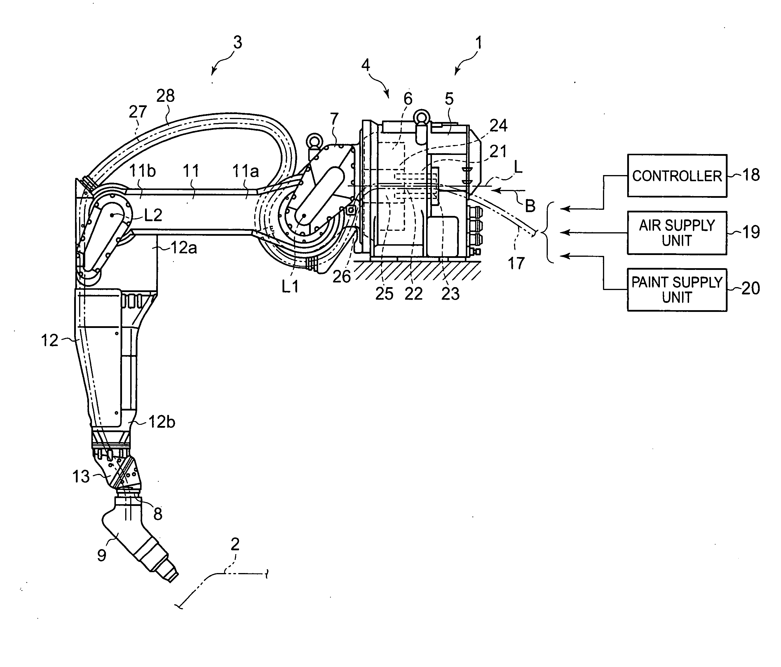
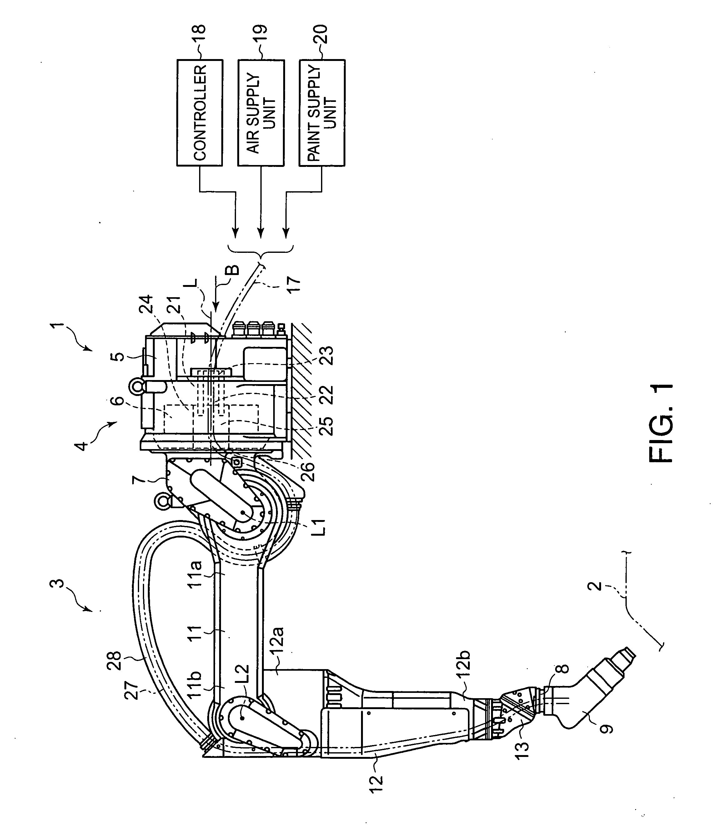
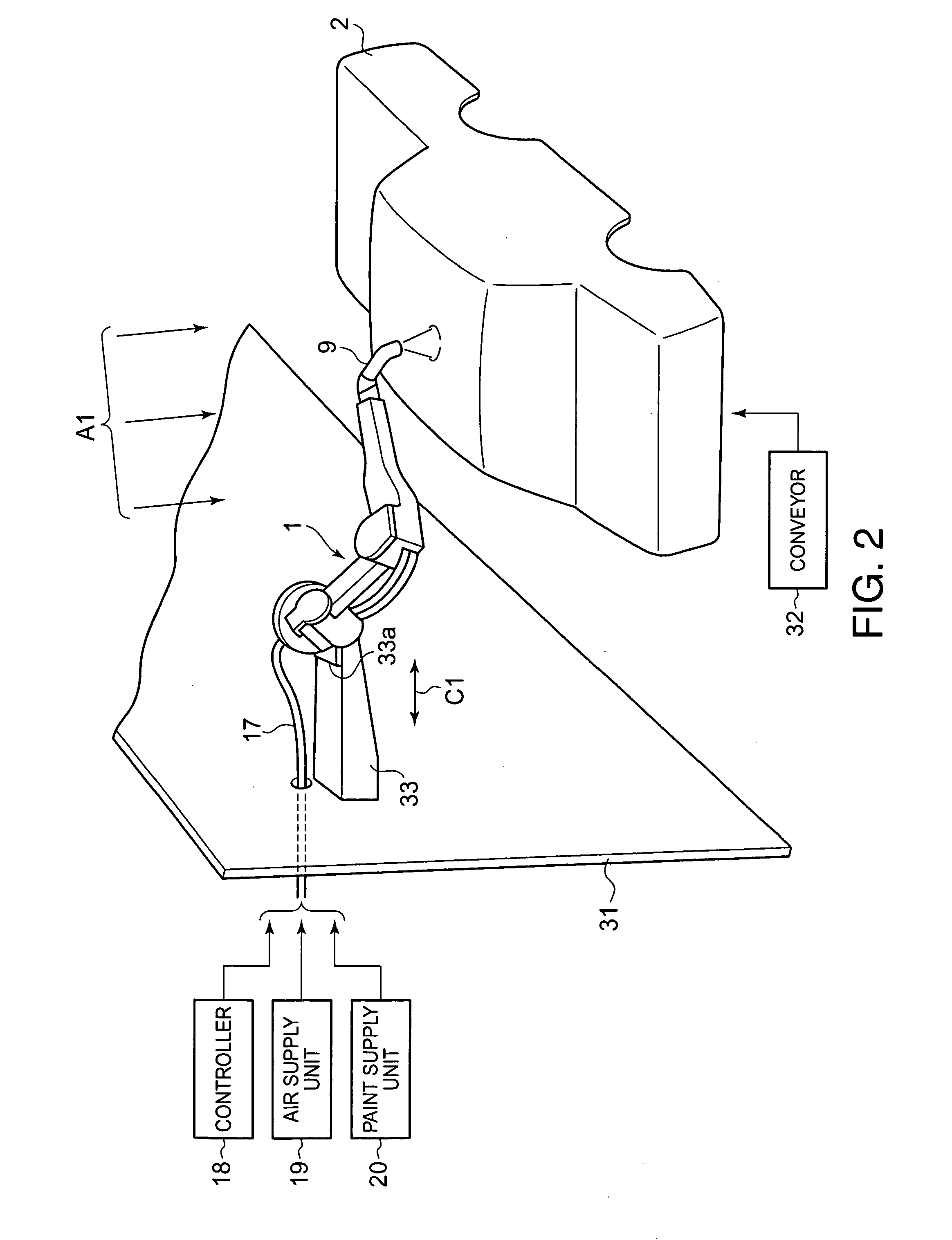
[0044] A painting robot 1 of a preferred embodiment according to the present invention shown in FIG. 1 is used for painting a workpiece 2, such as an automotive body as shown in FIG. 2. The painting robot 1 sprays paint on a predetermined part of the workpiece 2 while the workpiece 2 is being conveyed. The painting robot 1 has a robot arm 3 and a body structure 4.

[0045] The body structure 4 includes a stationary base unit 5 and a swivel unit (movable unit) 6. The stationary base unit 5 is fixedly installed at a predetermined position. The swivel unit 6 is driven for turning relative to the stationary base unit 5 about an axis L of rotation. The swivel unit 6 is on one side of the stationary base unit 5 on the axis L of rotation.

[0046] The robot arm 3 has a base part 7 and a front end part 8. The base part 7 of the robot arm 3 is fixed to the swivel unit 6 of the body structure 4. The base part 7 turns together with the swivel unit 6 about the axis L of rotation. The base part 7 is...


PUM


Abstract

A robot includes a body structure on which a robot arm having an end effector is rotatably supported. The body structure has a stationary base unit fixedly installed and a movable unit rotatably supported on the stationary base unit to turn about an axis of rotation. The stationary base unit includes a stationary-side guide part having a stationary-side internal space in which a flexible, elongate member connected to the robot arm or the end effector is extended loosely along the axis of rotation. The stationary-side guide part opens upstream in an elongate member inserting direction. The movable unit includes a movable-side guide part having a movable-side internal space in which the elongate member is extended loosely along the axis of rotation. The movable-side guide part opens downstream in an elongate member inserting direction. The stationary-side and the movable-side internal spaces communicate with each other.

Description

CROSS REFERENCE TO RELATED APPLICATIONS [0001] This application is based upon the prior Japanese Patent Application No. 2004-281941 filed on Sep. 28, 2004, the entire contents of which are incorporated herein by reference. BACKGROUND OF THE INVENTION [0002] 1. Field of the Invention [0003] The present invention relates to an industrial robot and, more particularly, to a painting robot. [0004] 2. Description of the Related Art [0005] An industrial robot mentioned in JP-A 7-108485 includes a body structure which has a stationary base unit as a stationary part thereof and a robot swivel unit as a movable part thereof. The robot swivel unit is supported on the stationary base unit for turning about an axis of rotation relative to the stationary base unit. Through holes are formed through the stationary base unit and the swivel unit coaxially with the axis of rotation. Cables and such, namely, elongate members, connected to a robot arm are extended through the through holes. An opening i...

Claims


Application Information

Patent Timeline
Patent Type & Authority Applications(United States)
IPC IPC(8): B05C5/00
CPCB05B13/0457B25J19/0029
Inventor INADA, TAKAHIROTSUJIMORI, TOSHIYUKIKITAMURA, SHINJITANIUCHI, RYOU
Owner KAWASAKI HEAVY IND LTD
Why Eureka
Try Eureka