Focusing mechanism for a vision detector

a technology of focusing mechanism and detector, which is applied in the direction of camera focusing arrangement, printers, instruments, etc., can solve the problems of human error risk, difficult arrangement of photodetectors, and difficulty in automatic inspection using photodetectors

Inactive Publication Date: 2006-05-18
COGNEX TECH & INVESTMENT
View PDF18 Cites 25 Cited by
  • Summary
  • Abstract
  • Description
  • Claims
  • Application Information

AI Technical Summary

Benefits of technology

[0046] This invention provides a focusing mechanism for a vision detector or machine vision system that provides the capability for remotely adjusting focus without disturbing a production environment. In one aspect of the invention, a machine vision system or vision detector is contained in a housing, with a window or protective transparent cover exposing the lens and imager. The imager and lens and window aligned on an

Problems solved by technology

Automatic inspection using photodetectors can be difficult since simple sensing of light intensity reflected from a point on the object is often insufficient for inspection.
Further, it may be hard to arrange the photodetectors when many points on an object need to be inspected.
Interference may be due to space limitations, crosstalk from the light sources, or other factors.
The cost of performing a line changeover, and the risk of human error involved, often offset the low cost and simplicity of the photodetectors.
This requirement may add additional cost and complexity that can offset the low cost and simplicity of the photodetectors.
Machine vision systems have disadvantages compared to an arrangement of photodetectors, including: They are relatively expensive, often costing ten times more than an arrangement of photodetectors.
They can be difficult to set up, often requiring people with specialized engineering training.
Furthermore, the decision time tends to vary

Method used


Image

  • Focusing mechanism for a vision detector
  • Focusing mechanism for a vision detector
  • Focusing mechanism for a vision detector

Examples


Embodiment Construction

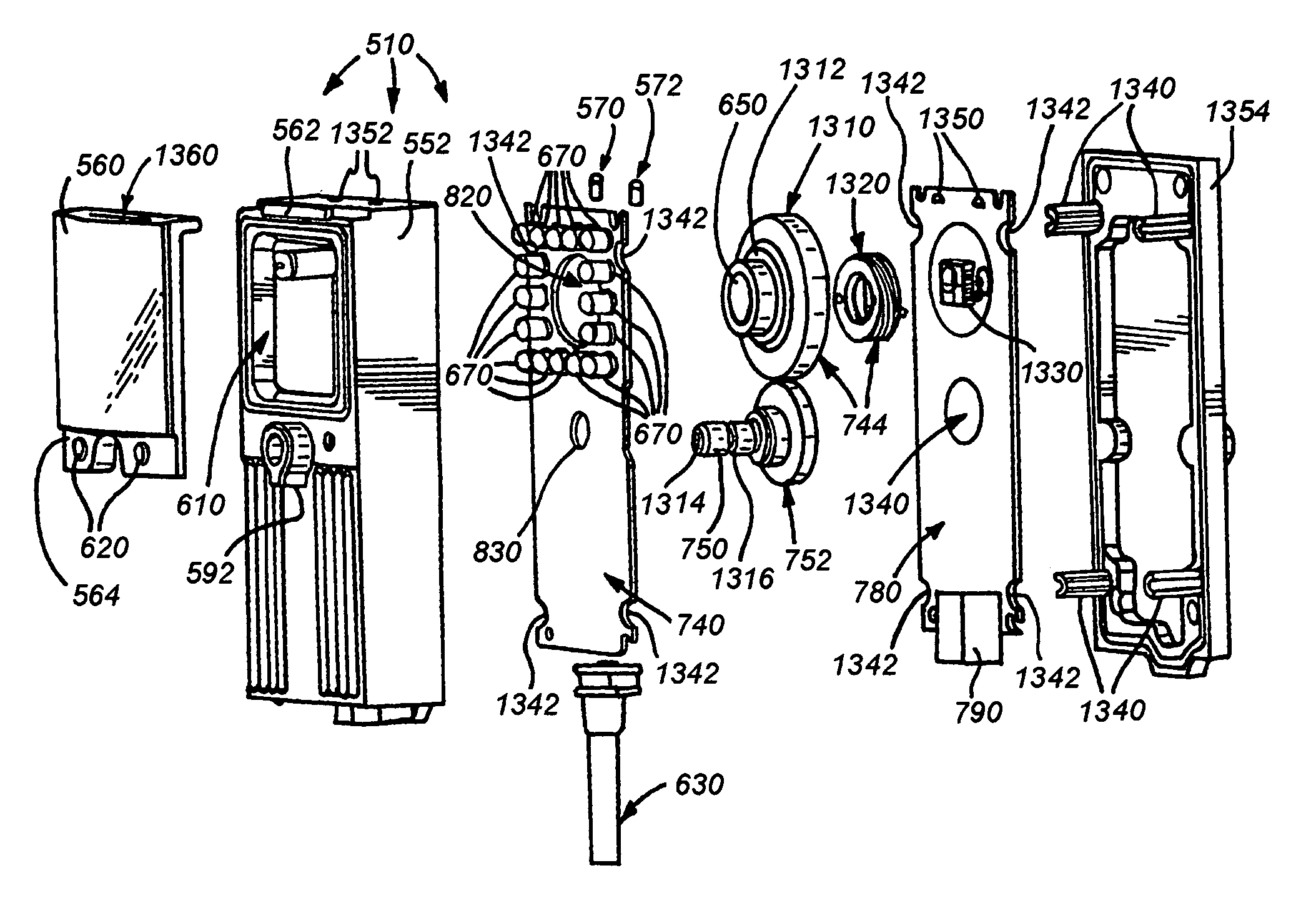
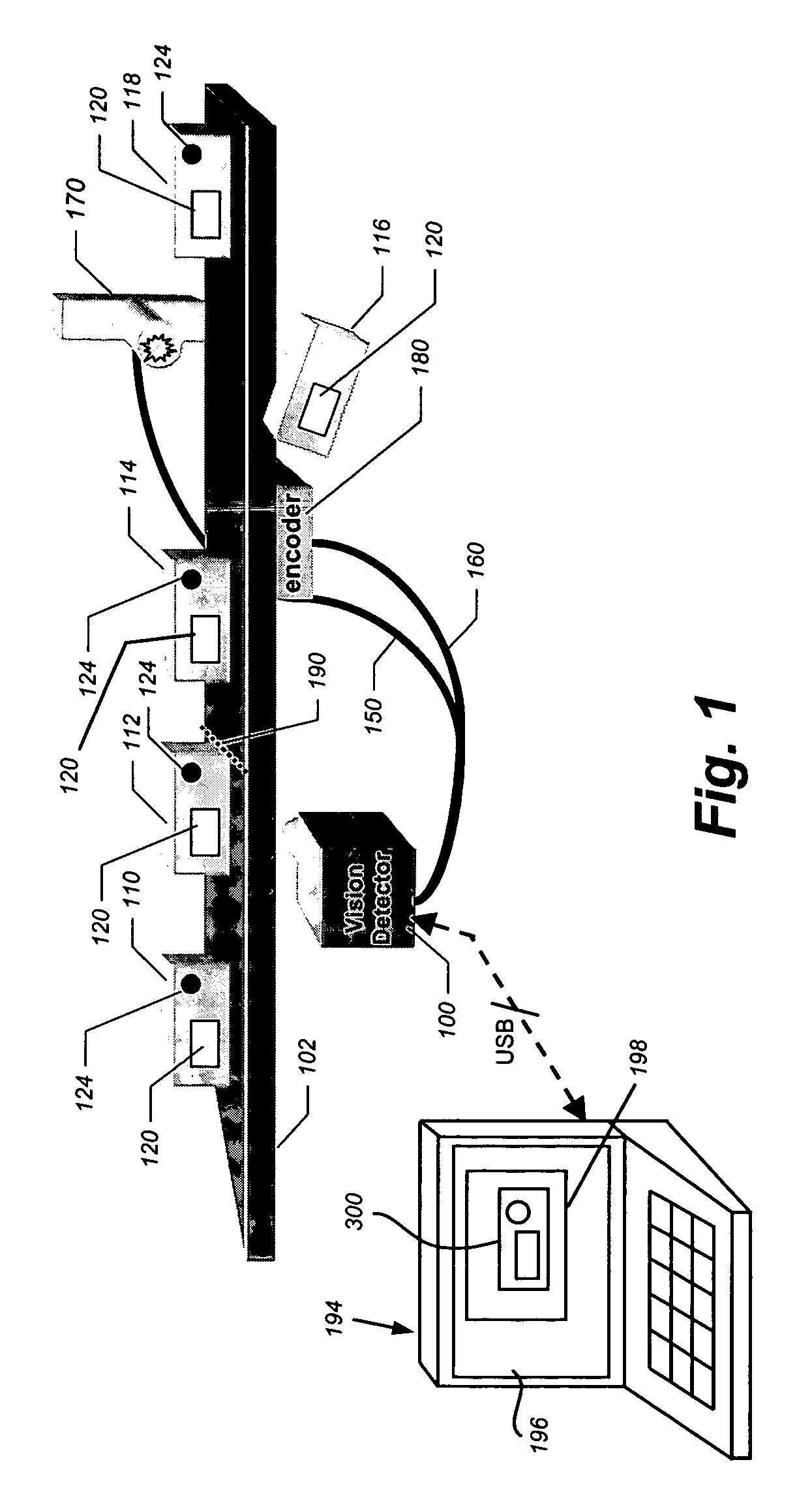
[0067] A vision detection and inspection apparatus (termed “vision detector” herein) 510 is shown in FIG. 5. The vision detector 510 of this illustrative embodiment functions generally in accordance with principles described in the above-incorporated-by-reference METHOD AND APPARATUS FOR VISUAL DETECTION AND INSPECTION OF OBJECTS, by William M. Silver, and summarized above in connection with the exemplary vision detector 100 (FIG. 1). In this illustration, the vision detector 510 of the illustrative embodiment is mounted along a moving (arrow 512) production line characterized by a conveyor 514. Alternatively, the line can be stationary and the vision detector may move. In any case, there is a relative motion between objects on the line and the vision detector 510. The production line features a stream of manufactured objects 520 and 522 each passing through the field of view of the vision detector 510 in succession. In this illustration the object 520 is presently in the field of v...


PUM


Abstract

A machine vision image acquisition system is provided with a housing or enclosure that protects the acquisition system components from an industrial environment. The machine vision image acquisition system has a focusing mechanism that can be actuated externally to the housing. The focusing mechanism uses a gear drive to transmit externally actuated focus adjustments to the optical components of the acquisition system.

Description

BACKGROUND OF THE INVENTION [0001] 1. Field of the Invention [0002] This invention relates to industrial machine vision inspection of objects, and more particularly to a focus adjustment mechanism that permits focus adjustment of optical components of a vision detector. [0003] 2. Description of the Related Art [0004] Industrial manufacturing relies on automatic inspection of objects being manufactured. One form of automatic inspection that has been in common use for decades is based on optoelectronic technologies that use electromagnetic energy, usually infrared or visible light, photoelectric sensors, and some form of electronic decision making. [0005] One well-known form of optoelectronic automatic inspection uses an arrangement of photodetectors. A typical photodetector has a light source and a single photoelectric sensor that responds to the intensity of light that is reflected by a point on the surface of an object, or transmitted along a path that an object may cross. A user-a...

Claims


Application Information

Patent Timeline
IPC IPC(8): H04N5/225
CPCH04N5/2252H04N5/2254H04N5/2256H04N23/55H04N23/56H04N23/51
Inventor COSTIGAN, GEORGEGOODSPEED, STEVEN N.KING, DAVID R.TREMBLAY, ROBERT J. IIKEATING, JOHN F.PHILLIPS, BRIAN S.HOFFMASTER, JAMES
Owner COGNEX TECH & INVESTMENT
Why Eureka
Try Eureka