Portable air compressor tool carrier

a tool carrier and air compressor technology, applied in the direction of positive displacement liquid engines, piston pumps, liquid fuel engines, etc., can solve the problems of laborious and laborious, cumbersome transportation of air compressor components and other materials necessary to perform a particular job, and loss of work tim

Inactive Publication Date: 2006-05-18
BLACK & DECKER INC
View PDF72 Cites 10 Cited by
  • Summary
  • Abstract
  • Description
  • Claims
  • Application Information

AI Technical Summary

Problems solved by technology

Transportation of air compressor components and other materials necessary to perform a particular job is often cumbersome due to the lack of a storage compartment on the air compressor assembly.
Such limitation causes the user to have to carry components separate from the air compressor assembly as well as find storage space for such components once at the worksite.
Further, sinc

Method used


Image

  • Portable air compressor tool carrier
  • Portable air compressor tool carrier
  • Portable air compressor tool carrier

Examples


Embodiment Construction

[0016] Reference will now be made in detail to the presently preferred embodiments of the invention, examples of which are illustrated in the accompanying drawings.

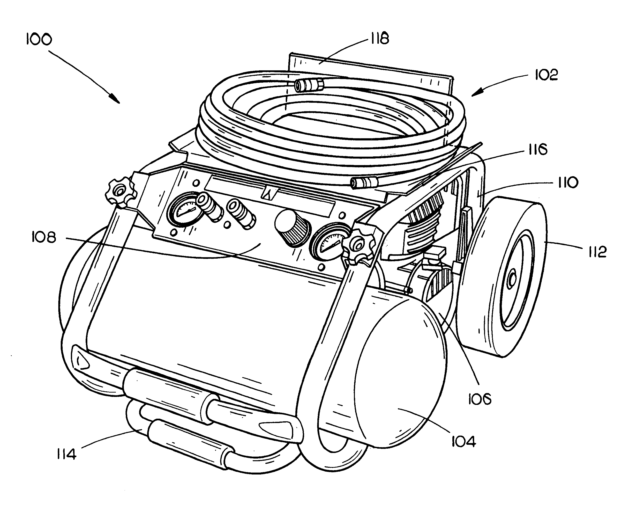
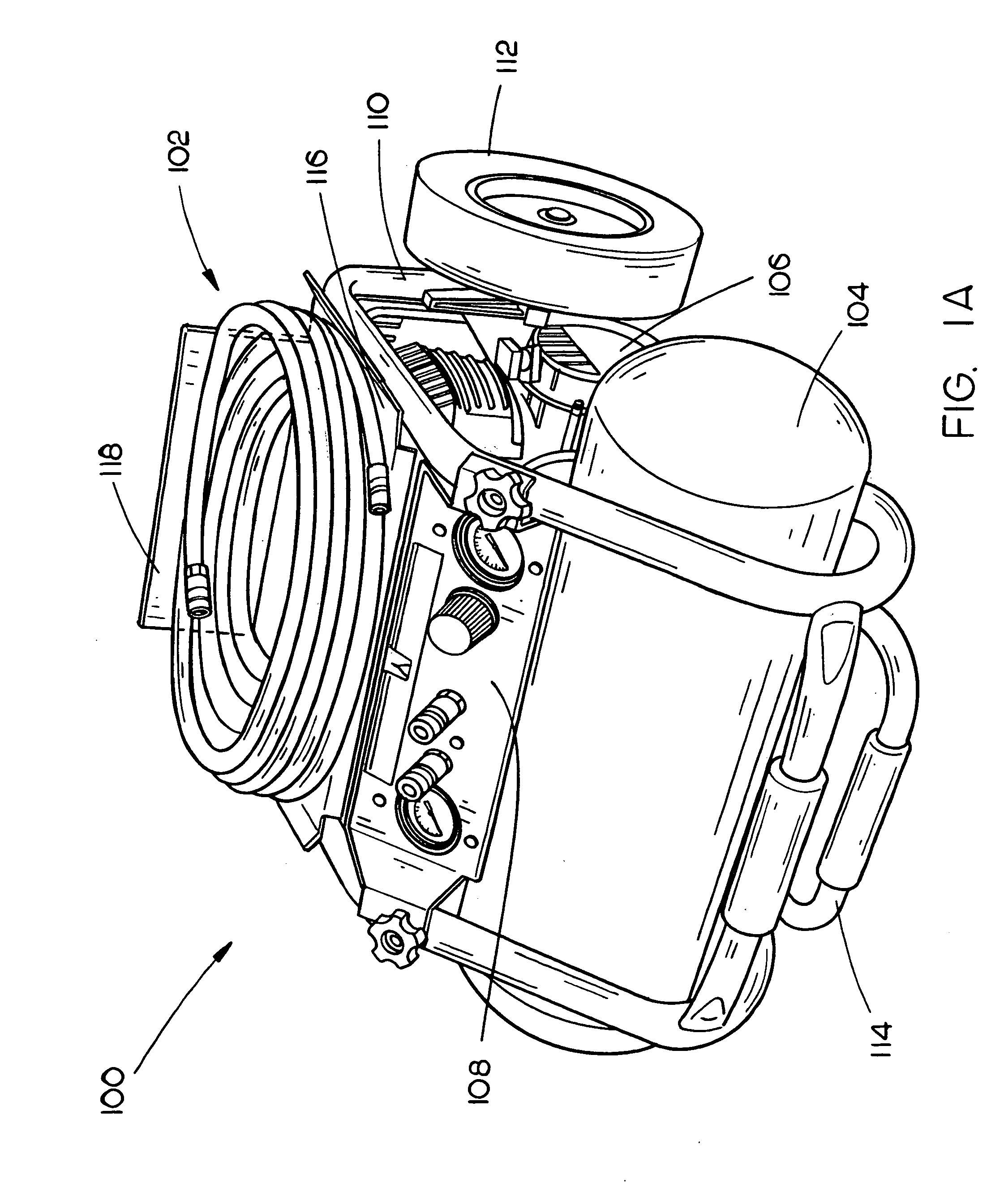
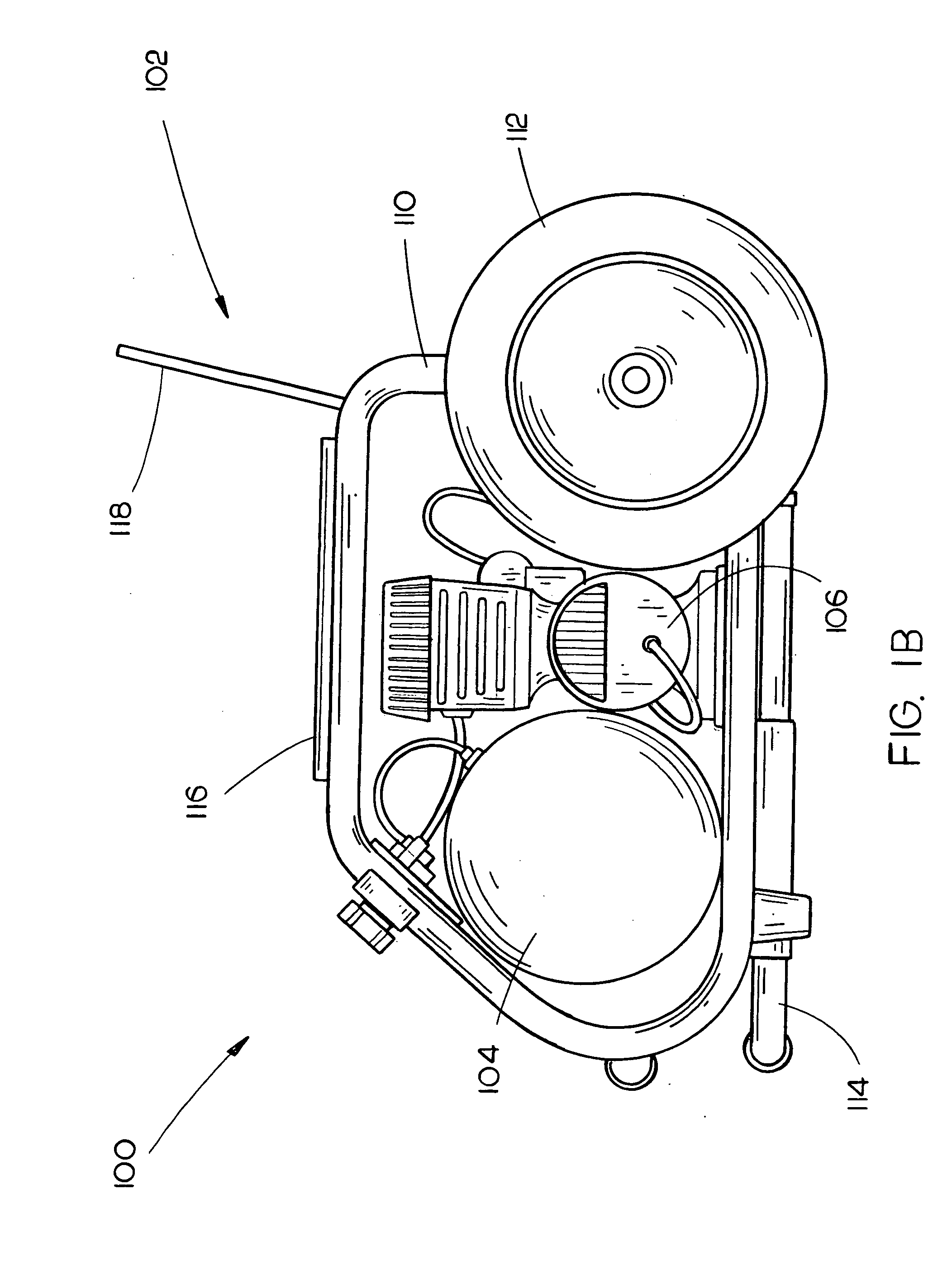
[0017] Referring specifically to FIGS. 1A and 1B, an air compressor assembly 100 including a tool carrier 102 in accordance with an exemplary embodiment of the present invention is shown. The air compressor assembly 100 includes an air storage tank 104 for storing compressed air, an air compressor 106 for supplying compressed air to the air storage tank 104, and a manifold assembly 108 for controlling and distributing compressed air from the air compressor assembly 100 to one or more air-powered tools. In exemplary embodiments, the manifold assembly 108 may be removable.

[0018] As shown in FIGS. 1A and 1B, the air compressor assembly 100 is equipped with a frame or roll cage 110 that at least substantially surrounds the air storage tank 104 and the air compressor 106 providing a surface area to which various air compress...


PUM


Abstract

The present invention is directed to a portable air compressor assembly including a tool carrier. In an embodiment, the portable air compressor assembly includes an air tank for storing compressed air and a compressor for supplying compressed air to the air tank. Further, a frame is coupled to the air tank and compressor providing an area for which the air tank and compressor may be mounted. In such embodiment, a pair of wheels are pivotally mounted to the frame allowing for inclined transportation of the air compressor assembly. In an embodiment, the tool carrier assembly includes a pan support coupled to the frame for providing a support surface for an air compressor accessory and work material. In addition, a tool support is coupled to the pan support for providing an additional support surface for the air compressor accessory and work material. The tool support includes at least one strap.

Description

CROSS-REFERENCE TO RELATED DOCUMENTS [0001] The present application claims the benefit under 35 U.S.C. § 119(e) of U.S. Provisional Patent Application Ser. No. 60 / 540,755, entitled “Air Compressor Tool Carrier,” filed Jan. 30, 2004 which is herein incorporated by reference in its entirety. The present application is a continuation-in-part under 35 U.S.C. § 120 of U.S. applications Ser. Nos. 10 / 410,129, filed on Apr. 9, 2003, 29 / 179,391, filed on Apr. 9, 2003, and 10 / 444,708, filed on May 23, 2003. The present application incorporates the following applications by reference in their entirety: U.S. application Ser. No. 10 / 410,129, filed Apr. 9, 2003; U.S. Application Ser. No. 29 / 179,391, filed Apr. 9, 2003; U.S. Provisional Application Ser. No. 60 / 469,645, filed May 12, 2003; U.S. application Ser. No. 10 / 444,708, filed May 23, 2003; China Patent Serial No. 2L 03358051, filed Aug. 27, 2003; China Application Serial No. 03156352.X, filed Sep. 4, 2003; U.S. Provisional Application Ser. N...

Claims


Application Information

Patent Timeline
IPC IPC(8): F04B53/00F04B35/04
CPCF04B35/06F04B41/02
Inventor ETTER, MARKMORGAN, FREDRICKHANSON, CHADVINTZEL, JAMES
Owner BLACK & DECKER INC
Why Eureka
Try Eureka