Bone screw

a bone screw and screw head technology, applied in the field of bone screws, can solve the problems of a problem with the use of such bone screws, and achieve the effect of extending the pivot angl

Inactive Publication Date: 2006-05-18
BIEDERMANN TECH GMBH & CO KG
View PDF85 Cites 230 Cited by
  • Summary
  • Abstract
  • Description
  • Claims
  • Application Information

AI Technical Summary

Problems solved by technology

The use of such bone screws is something of a problem in the region of cervical vertebrae.

Method used


Image

  • Bone screw
  • Bone screw

Examples


Embodiment Construction

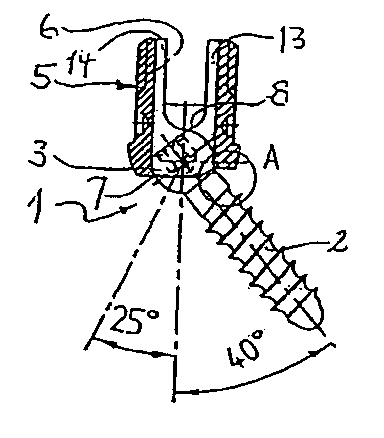
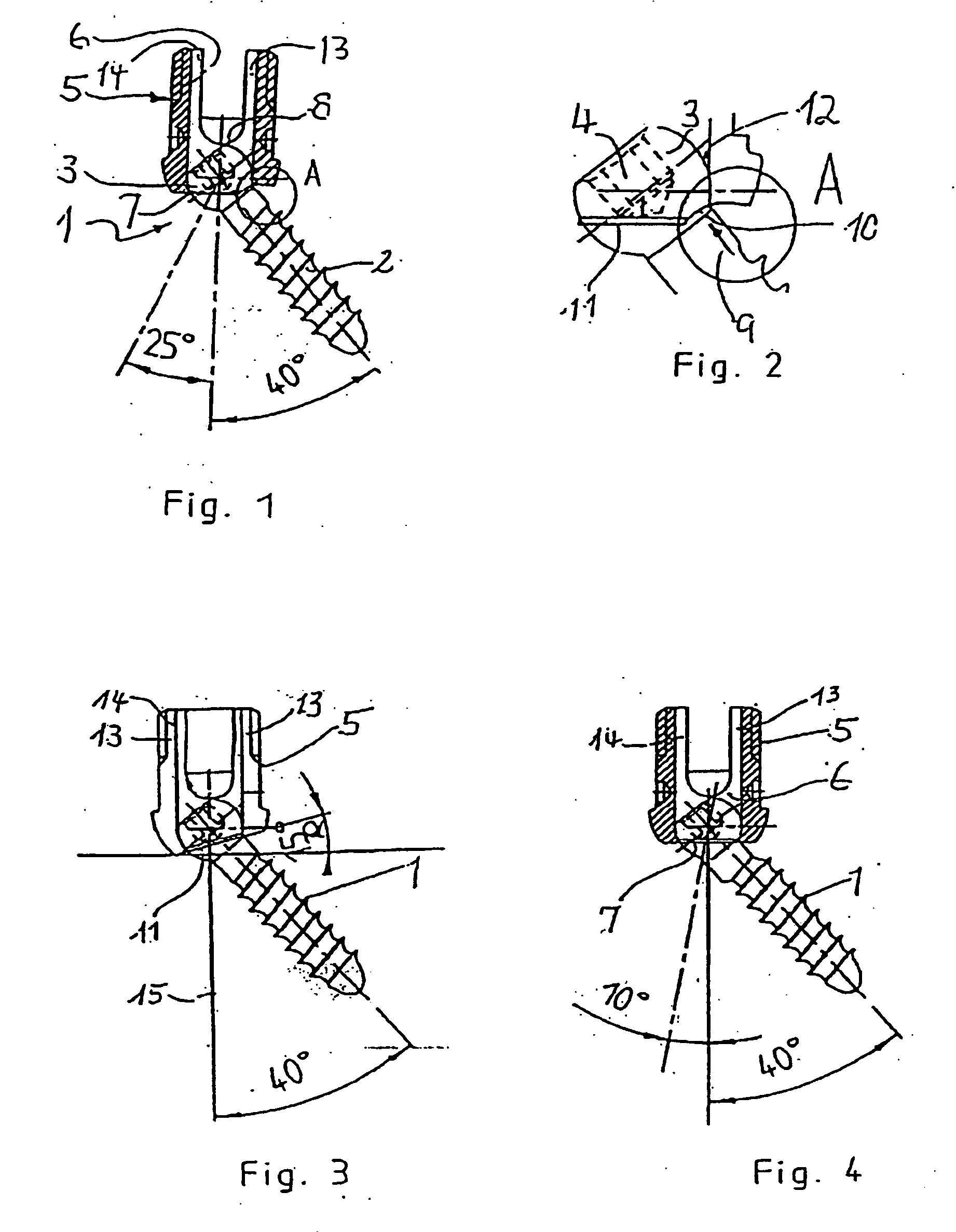
[0012] The bone screw includes a screw member proper 1 having a threaded section 2 and a head 3. The head is formed in the shape of a segment of a sphere in the region adjoining the threaded section. Coaxial with the thread axis and on the end opposite to the threaded section 2 the head possesses a recess 4 for engagement with a socket screw key.

[0013] The bone screw further comprises a cylindrically constructed receiving part 5. At one end this has a first bore 6 of axially symmetrical construction. On the opposite end a second bore 7 is provided whose diameter is greater than that of the threaded section 2 and smaller than that of the head 3. On the end opposite to the second bore the first bore is open and its diameter is of such a size that that the screw member 1 can be guided through the open end by its threaded section 2 going through this bore and by the head going as far as the bottom of the first bore. The bottom of the first bore is constructed as a spherically shaped re...


PUM


Abstract

A bone screw having a screw member possessing a threaded section and a head and a receiving part at the head end for receiving a rod to be connected to the bone screw is provided. The receiving part has on open first bore and a substantially U-shaped cross-section having two free legs provided with a thread. Furthermore, the receiving part has a second bore on the end opposite to the first bore whose diameter is greater than that of the threaded section and smaller than that of the head. On the bottom of the first bore a seat for the head is provided. In order that the screw member can be pivoted to at least one side by an enlarged angle, the edge bounding the free end of the second bore viewed relative to the axis of the first bore is of asymmetric construction.

Description

REFERENCE TO RELATED APPLICATIONS [0001] This application is a continuation of Ser. No. 10 / 763,431, filed Jan. 22, 2004, which is a continuation of Ser. No. 10 / 037,698, filed Nov. 9, 2001, now U.S. Pat. No. 6,736,820, the disclosures of which are incorporated herein by reference.FIELD AND BACKGROUND OF THE INVENTION [0002] The invention relates to a bone screw having a threaded section and a head and a receiving part at the head end for receiving a rod to be connected to the bone screw, the receiving part possessing an open first bore and a substantially U-shaped cross-section having two free legs provided with a thread and a second bore at the end opposite to the first bore, whose diameter is greater than that of the threaded section and smaller than that of the head and which forms the seat for the head, and a nut or screw working together with the thread. [0003] Such a bone screw is disclosed, for example, in U.S. Pat. No. 5,672,176. In the known bone screw the head is of spheric...

Claims


Application Information

Patent Timeline
Patent Type & Authority Applications(United States)
IPC IPC(8): A61F2/30A61B17/70F16B35/00F16B35/06
CPCA61B17/7032A61B17/7067A61B17/7038A61B17/7037A61B17/70A61B17/8605
Inventor BIEDERMANN, LUTZHARMS, JURGEN
Owner BIEDERMANN TECH GMBH & CO KG
Why Eureka
Try Eureka