Apparatus, method and computer program product for monitoring AC line current through the step start resistors of a high voltage power supply

a technology of step start resistor and high-voltage power supply, which is applied in the direction of process and machine control, dynamo-electric converter control, instruments, etc., can solve the problems of aborting the process, not providing means to identify abnormal characteristics, and affecting the longevity of the tube or other devi

Inactive Publication Date: 2006-05-18
PL TECH
View PDF18 Cites 9 Cited by
  • Summary
  • Abstract
  • Description
  • Claims
  • Application Information

AI Technical Summary

Benefits of technology

[0006] The present invention recognizes that, in systems of this type where high voltages are employed, arcing or other fault conditions may occur during the step start interval as well as during normal operation, and that if such conditions occur during the step start interval the step start process should be aborted. The present invention further recognizes that, especially when faults or overloads occur during the step start, the step start process may be repeated several times in succession, allowing the step start resistors to become progressively hotter.

Problems solved by technology

Over the years, power supply systems have been developed for devices, such as high power electron tubes, etc, to provide a ‘step start’, so that full power is not immediately applied, which otherwise might have deleterious effects upon the longevity of the tubes or other devices.
However, as presently recognized, such conventional systems do not provide means to identify abnormal characteristics in the current feeding the power supply during the step start interval, or to cause the start process to be aborted if such abnormal characteristics are detected.
In addition, neither do such conventional systems provide means to identify when the step start resistors need longer cooling time due to higher than normal energy dissipation from overloads and frequent restarts.
In fact, step start systems, by their very nature, by limiting current during the step start interval also effectively limit the ability of any existing or separate protective circuitry to sense a current overload and to protect an associated load circuit, such as by opening a circuit breaker.

Method used


Image

  • Apparatus, method and computer program product for monitoring AC line current through the step start resistors of a high voltage power supply
  • Apparatus, method and computer program product for monitoring AC line current through the step start resistors of a high voltage power supply
  • Apparatus, method and computer program product for monitoring AC line current through the step start resistors of a high voltage power supply

Examples


Embodiment Construction

[0019] Referring now to the drawings, wherein like reference numerals designate identical or corresponding parts throughout the several views, and more particularly to FIGS. 1a-4 thereof, there are shown various embodiments of the present invention, as will now be described.

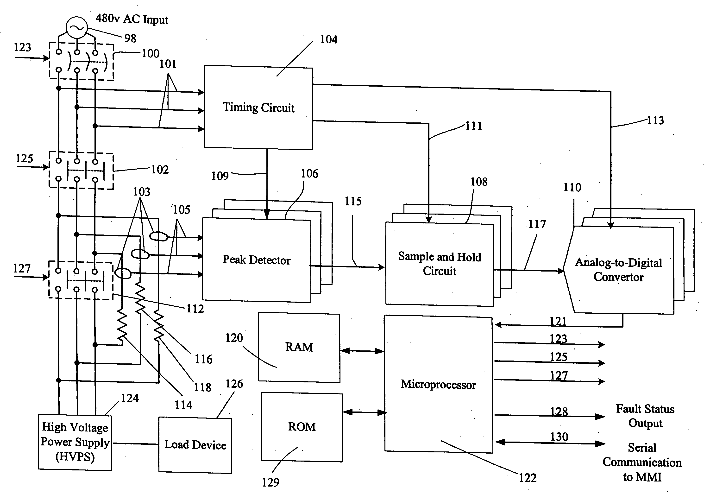
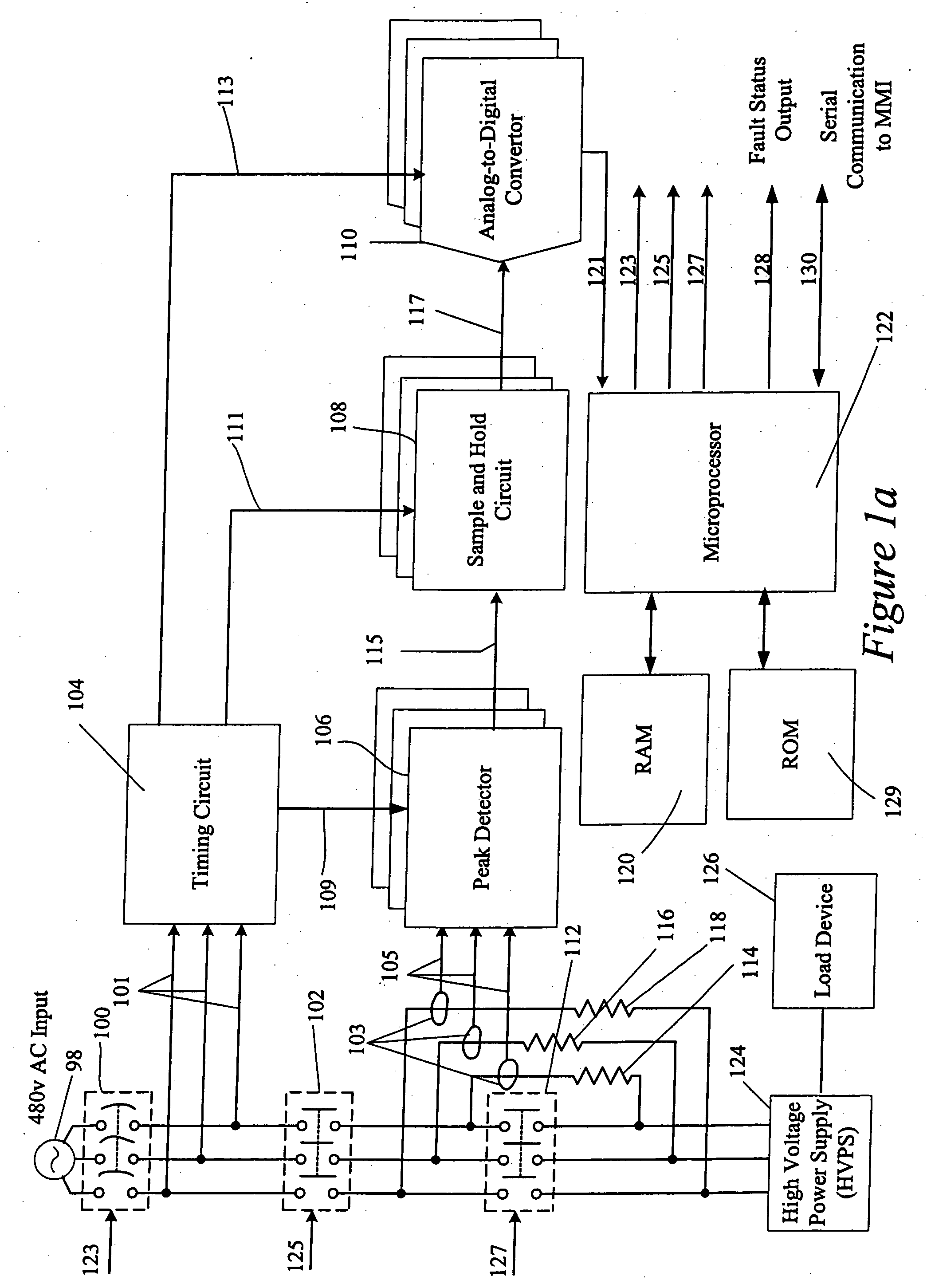
[0020]FIG. 1a is a block diagram of a first preferred embodiment of the present invention. In FIG. 1a, the system includes an external power source 98 (e.g., 480 V AC); a circuit breaker 100, a main contactor 102, a step contactor 112, step resistors 114, 116 and 118, a timing circuit 104, current sensors 103, peak detectors 106, sample and hold circuits 108, analog to digital convertors 110, a microprocessor 122, RAM (Random Access Memory) 120, ROM (Read Only Memory) 129, and a load comprising a High Voltage Power Supply (HVPS) 124 and a load device 126 supplied therefrom. The high voltage power supply 124 may provide the beam power supply to a high power transmitting electron tube such as a klystrode (a hybrid...


PUM


Abstract

A circuit to monitor ac line current through resistors employed to provide a ‘step start’ in a power supply, including means to monitor the current flowing through the step start resistors, comprising a peak detector, a sample and hold circuit, an analog to digital convertor and a microprocessor. The output of the current monitoring circuit may be employed to abort starting if abnormalities are sensed. The circuit may also be used to identify when the step start resistors need longer cooling time, and to continuously monitor current at times other than during starting. A timing circuit is also incorporated, which senses zero crossings of the voltage input to the power supply, so as to control the timing of the current monitoring circuit. The discrete circuits employed may be replaced by either a digital signal processor integrated circuit or a general-purpose computer implementing the same steps in a suitable algorithm.

Description

BACKGROUND OF THE INVENTION [0001] 1. Field of the Invention [0002] The present invention generally relates to monitoring circuits for power supplies. More particularly, the present invention relates to an apparatus, method and computer program product for monitoring AC line current through the step start resistors of a high voltage power supply, which may be employed with devices such as high power transmitting tubes, etc. [0003] 2. Discussion of the Background [0004] Over the years, power supply systems have been developed for devices, such as high power electron tubes, etc, to provide a ‘step start’, so that full power is not immediately applied, which otherwise might have deleterious effects upon the longevity of the tubes or other devices. Such systems typically initially insert current limiting devices, such as starting resistors or ‘step start’ resistors, into the supply circuits to limit the current for a predetermined time interval, which will be referred to herein as the ‘...

Claims


Application Information

Patent Timeline
Patent Type & Authority Applications(United States)
IPC IPC(8): H02H3/08G06F1/30
CPCG06F1/30
Inventor SEE, ALVIN B.CORREA, PAULO
Owner PL TECH
Why Eureka
Try Eureka