
Wheel suspension for vehicles

a technology for suspensions and wheels, applied in the direction of suspension arms, resilient suspensions, vehicle components, etc., can solve the problems of correspondingly greater problems for vehicles with twin fronts, and the toe-in of front wheels can vary, so as to simplify the steering system and simplify the interface. flexible and flexible

Inactive Publication Date: 2006-06-01
VOLVO LASTVAGNAR AB
View PDF9 Cites 9 Cited by
  • Summary
  • Abstract
  • Description
  • Claims
  • Application Information

AI Technical Summary

Benefits of technology

[0006] An object of the present invention is to produce a wheel suspension which allows easier and more compact packing, and also which counteracts brake steering and other problems with wheel axle angles.

Problems solved by technology

This contributes to problems with the packing of other components and equipment which have to be mounted on and around the frame.
The problem is especially great in connection with front-wheel suspensions, where components for suspension and steering have to be adapted to the space for the engine.
The problems are correspondingly greater for vehicles with twin front axles where two leaf spring assemblies carry a bogie suspension with two axles.
For vehicles with bogie suspension, problems of variation in the toe-in of the front wheels can arise on account of different stiffness in the spring assemblies.
Each such component added to the wheel suspension increases the weight of the vehicle.
The conventional solution with an axle mounted in the center of a leaf spring assembly can also give rise to further problems.

Method used


Image

  • Wheel suspension for vehicles
  • Wheel suspension for vehicles
  • Wheel suspension for vehicles

Examples


Embodiment Construction

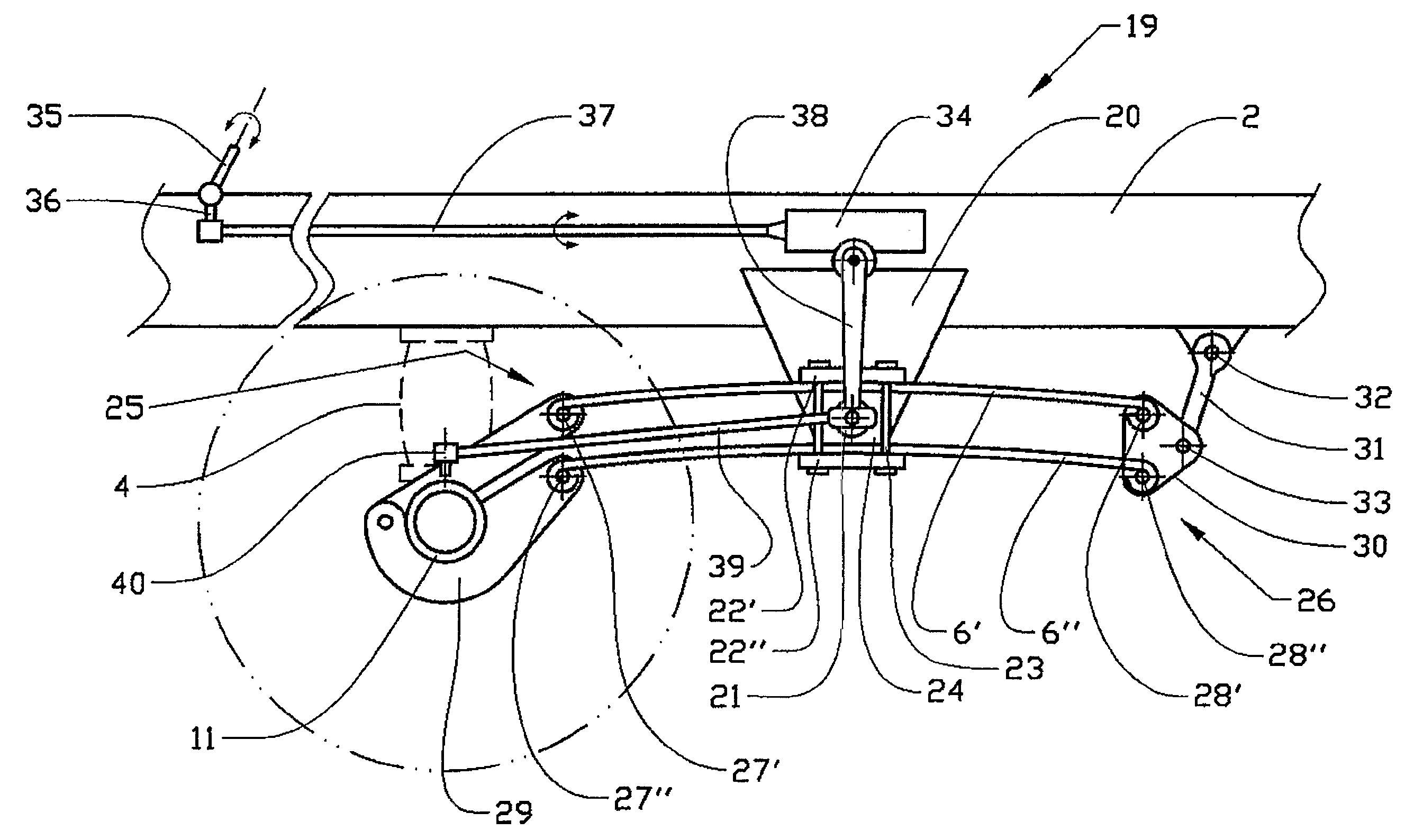
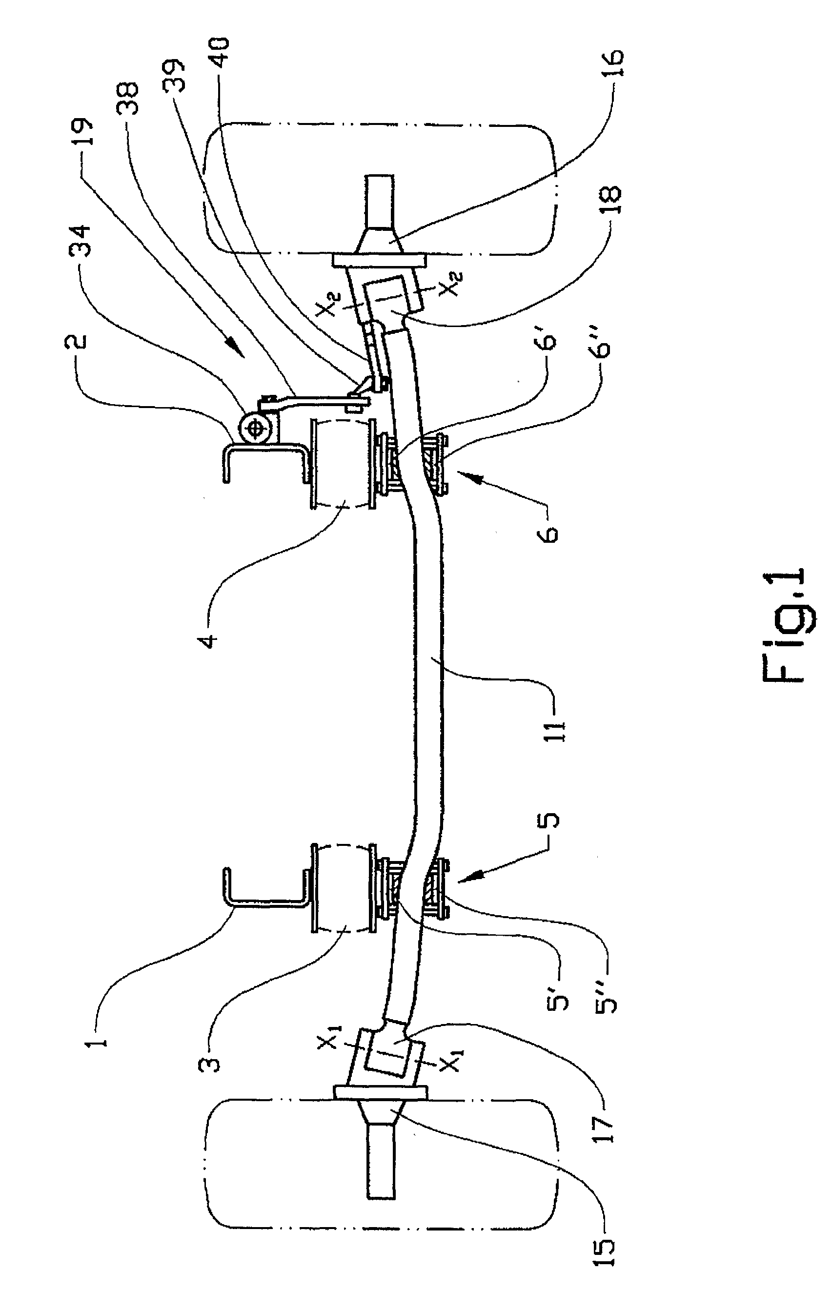
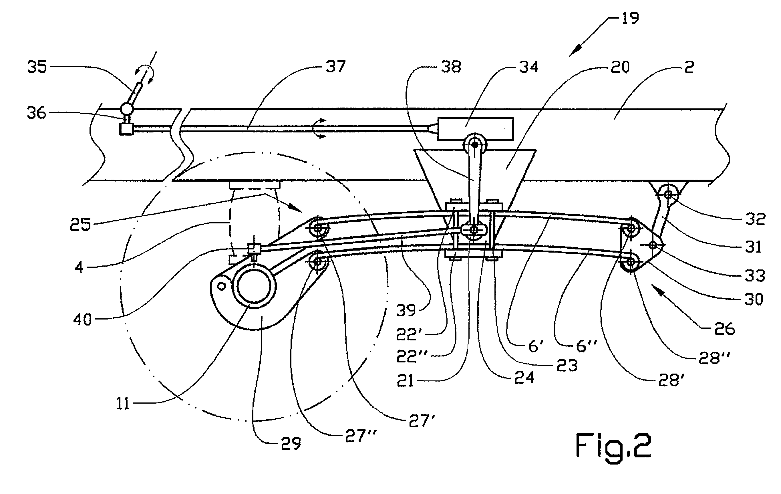
[0028]FIG. 1 shows a diagrammatic wheel suspension for a vehicle constructed on a frame which includes of two longitudinal beams 1, 2, in this case a pair of U-beams. The lower sections of the beams rest on a pair of damper devices in the form of air bellows 3,4. Each air bellows 3,4 is mounted in conjunction with one end of a leaf spring assembly 5,6, each leaf spring assembly comprising a pair of parallel leaf springs 5′, 5″; 6′, 6″. The leaf spring assemblies 5,6 are mounted in the longitudinal direction of the beams 1,2, with the leaf springs 5′, 5″ and 6′, 6″ arranged in pairs positioned at an, on the whole, constant distance from one another. The distance is on the whole constant in the unloaded state, when the vehicle is stationary. However, the mounting of the leaf spring assembly is intended to counteract the distance being changed when the springs are loaded.

[0029] The leaf spring assemblies 5,6 support a rigid axle 11 arranged transversely to the longitudinal axis of the...


PUM


Abstract

A wheel suspension for vehicles that includes leaf spring assemblies mounted in pairs on each side of the vehicle in the longitudinal direction of the vehicle and also at least one damper device mounted on the vehicle in conjunction with at least one wheel axle. The wheel suspension also has a central section of each leaf spring assembly which is mounted rotatably relative to an attachment device fixed to the vehicle, the ends of each leaf spring assembly being attached movably relative to the vehicle, where at least one of the ends of each leaf spring assembly supports a wheel axle and a damper device.

Description

CROSS-REFERENCE TO RELATED APPLICATIONS [0001] The present application is a continuation patent application of International Application No. PCT / SE2004 / 000370 filed 15 Mar. 2004 which was published in English pursuant to Article 21(2) of the Patent Cooperation Treaty, and which claims priority to Swedish Application No. 0301191-3 filed 24 Apr. 2003. Said applications are expressly incorporated herein by reference in their entireties.TECHNICAL FIELD [0002] The present invention relates to wheel suspensions for vehicles, and in particular for heavy-duty vehicles in which the wheel suspension includes leaf springs. BACKGROUND OF THE INVENTION [0003] Wheel suspensions including leaf springs are common for heavy-duty vehicles, especially for vehicles built on a frame made of longitudinal beams. Two or more leaf springs are as a rule mounted in the form of a leaf spring assembly attached at its ends to the underside of the frame. In order to allow a resilient movement of an axle mounted i...

Claims


Application Information

Patent Timeline
Patent Type & Authority Applications(United States)
IPC IPC(8): B60G11/46B60G7/00B60GB60G5/03B60G5/04B60G5/053
CPCB60G5/04
Inventor PREIJERT, STEFAN
Owner VOLVO LASTVAGNAR AB
Learn More