Optical fiber connector

a technology connectors, applied in the field of optical fiber connectors, can solve the problems of optical fiber failing altogether, degrading the transmission performance of optical fiber, and so as to minimize the snagging of the connector latching arm and facilitate the operation of the latching arm. , the effect of small form

Inactive Publication Date: 2006-06-01
CORNING CABLE SYST LLC
View PDF24 Cites 91 Cited by
  • Summary
  • Abstract
  • Description
  • Claims
  • Application Information

AI Technical Summary

Benefits of technology

[0007] According to the present embodiment, a subassembly comprising a ferrule holder, a ferrule and a lead-in tube, the ferrule and the lead-in tube are disposed within the ferrule holder and the subassembly is inserted into the housing passage through the housing first end. A spring element is disposed between a shoulder within the housing passage and a flange on the ferrule holder and a retainer is inserted into the housing passage through the housing first end for retaining the subassembly within the housing. Preferably, the optical fiber connector housing further comprises a latching arm for latching the optical fiber connector to an optical fiber connector adapter or other piece of optical fiber hardware. The insertion of such components as the subassembly,...

Problems solved by technology

If the stress angle is large enough, the high stress level at the attachment member/housing joint may cause the joint to fail and the attachment member to separate from the rest of ...

Method used


Image

  • Optical fiber connector
  • Optical fiber connector
  • Optical fiber connector

Examples


Embodiment Construction

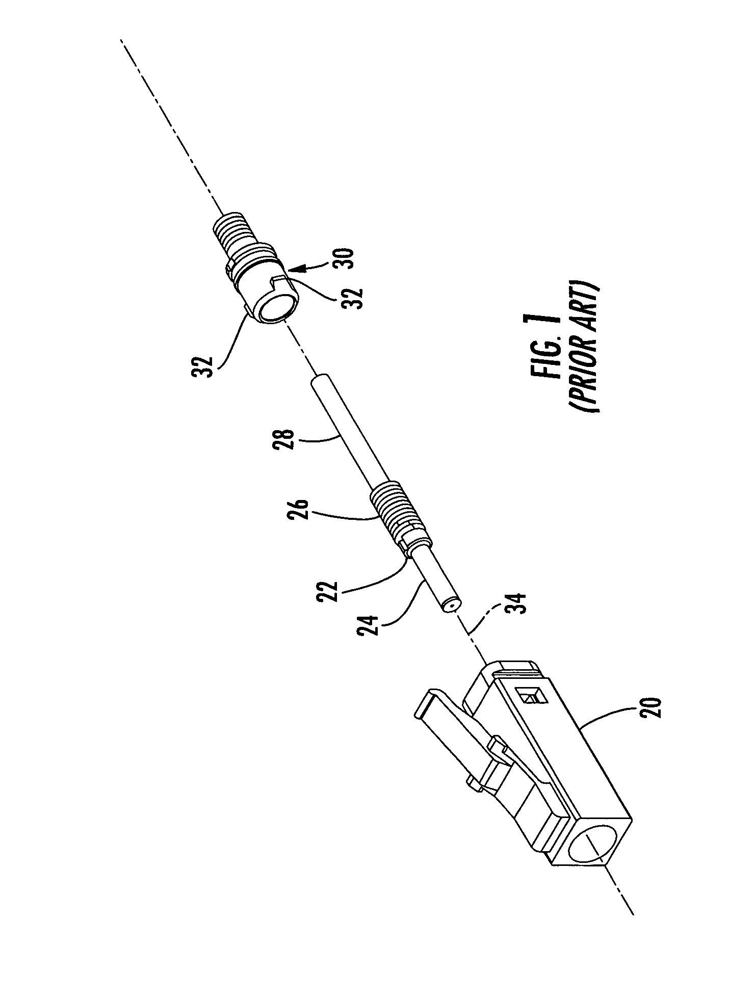
[0048]FIG. 1 depicts a prior art LC connector comprising, inter alia, a housing 20, a ferrule holder 22 having a ferrule 24 disposed within the ferrule holder, a spring 26, a lead-in tube 28 and a separate attachment member 30. The prior art connector of FIG. 1 is assembled by inserting ferrule holder 22 (including ferrule 24 and lead-in tube 28) and spring 26 through the rear of housing 20 and thereafter inserting attachment member 30, also through the rear of housing 20, until latching members 32 on attachment member 30 engage with corresponding openings in the housing. Attachment member 30 serves both to retain the ferrule holder within housing 20, and as a seat for spring 26, wherein the spring is seated against the attachment member and biases ferrule holder 22 forward. Attachment member 30 also provides a point of attachment for strength members which may accompany an optical fiber cable. Prior art connectors such as the connector illustrated in FIG. 1 suffer from a weakness a...


PUM


Abstract

Various exemplary embodiments of an optical fiber connector having a one-piece housing are shown and described. The housing includes a tailpiece which extends rearward from a housing body. The tailpiece provides a location for securing strength members which may be associated with an optical fiber or optical fiber cable attached to the optical fiber connector. The tailpiece is integral formed with the housing. Thus, stress applied to the optical fiber at an angle to the longitudinal axis of the connector will not result in a degradation of the connector mechanical or optical performance. The optical fiber connector components are advantageously inserted in the connector housing through the forward end of the housing and retained with a retainer.

Description

FIELD OF THE INVENTION [0001] The invention relates generally to an optical fiber connector, and more particularly to an optical fiber connector having a one-piece housing. TECHNICAL BACKGROUND [0002] Optical fibers are widely used in a variety of applications, including the telecommunications industry in which optical fibers are employed in a number of telephony and data transmission applications. Due, at least in part, to the extremely wide bandwidth and the low noise operation provided by optical fibers, the use of optical fibers and the variety of applications in which optical fibers are used are continuing to increase. For example, optical fibers no longer serve as merely a medium for long distance signal transmission, but are being increasingly routed directly to the home or, in some instances, directly to a desk or other work location. [0003] With the ever increasing and varied use of optical fibers, it is apparent that efficient methods of coupling optical fibers, such as to...

Claims


Application Information

Patent Timeline
IPC IPC(8): G02B6/38G02B6/36
CPCG02B6/3851G02B6/3869G02B6/3893G02B6/3861G02B6/3888
Inventor MUDD, RONALDJOHNSON, DEREK
Owner CORNING CABLE SYST LLC
Why Eureka
Try Eureka