Multiple synchronized optical sources for time-of-flight range finding systems

Active Publication Date: 2011-08-04
MICROSOFT TECH LICENSING LLC
View PDF99 Cites 5 Cited by
  • Summary
  • Abstract
  • Description
  • Claims
  • Application Information

AI Technical Summary

Benefits of technology

[0015]The present invention recognizes that in many applications it is desirable to augment the effective optical power emitted by a phase-based TOF system to direct more optical energy toward at least a region of the target object. Effective optical power augmentation is achieved in one embodiment by including at least one auxiliary wireless optical emitter (WOE) unit that is preferably optically and wirelessly dynamically synchronized in modulation frequency and in phase to the Sout emissions from the TOF system. The WOE units are disposed so as to illuminate at least a portion of the target object with their emitted optical energy. The optical power emitted by such units may be less than, greater than, or even the same as the Sout optical power emitted by the TOF system. An advantage of relatively low power WOE units is their reasonably small cost and form factor, and the ability to dispose them relatively close to the target object. The effective optical energy illumination provided by such unit(s) disposed close to the target object can be very substantial. Preferably each auxiliary optical emitter is a standalone unit, and may, but need not be, battery operated.
[0017]In a second embodiment, at least one auxiliary plug-wired optical emitter (PWOE) unit is physically removably attachable to the housing of the TOF system, preferably by a plug connection whose short wire length minimizes propagation delay. The plug connection enables a very short wire length to couple this PWOE to the drive signal to the TOF primary optical emitter. Circuitry within the TOF system examines the delay lag in an image acquired solely using each such PWOE unit, one at a time, and compares to an image acquired solely using the TOF primary optical emitter. The TOF system circuitry can compensate for the delay lag associated with data acquired using optical energy from each PWOE unit used in isolation and without optical energy from the primary optical unit. Alternatively, the TOF circuitry can tune the delay of each PWOE to match the delay of the primary optical unit. Any number of the thus properly delay-compensated or selected PWOE(s) can then be used in parallel with the TOF system primary optical source to increase the amount of optical energy falling upon the target object. A TOF system may employ at least one WOE and at least one PWOE unit, if desired.

Problems solved by technology

The effective illumination provided by Sout as seen by target object 120 varies inversely with the square of Z. Thus, increasing magnitude of output power from emitter 120 can enhance system 100 performance, providing more accurate measurements over increasing magnitudes of Z. However in some systems emitter 120 may be bonded to IC 110, such that replacing the emitter with a more powerful (higher wattage) device may be difficult.

Method used


Image

  • Multiple synchronized optical sources for time-of-flight range finding systems
  • Multiple synchronized optical sources for time-of-flight range finding systems
  • Multiple synchronized optical sources for time-of-flight range finding systems

Examples


Embodiment Construction

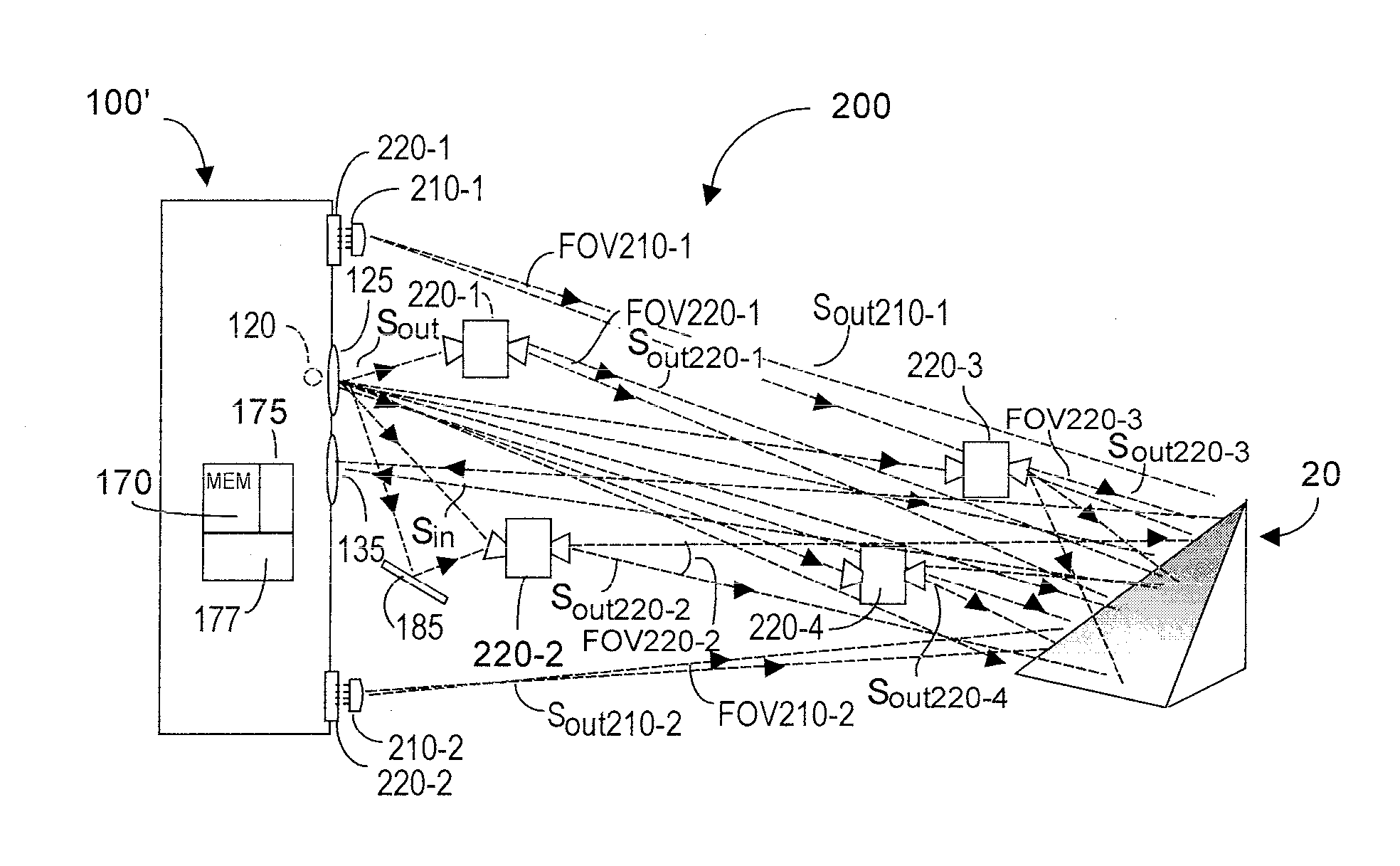
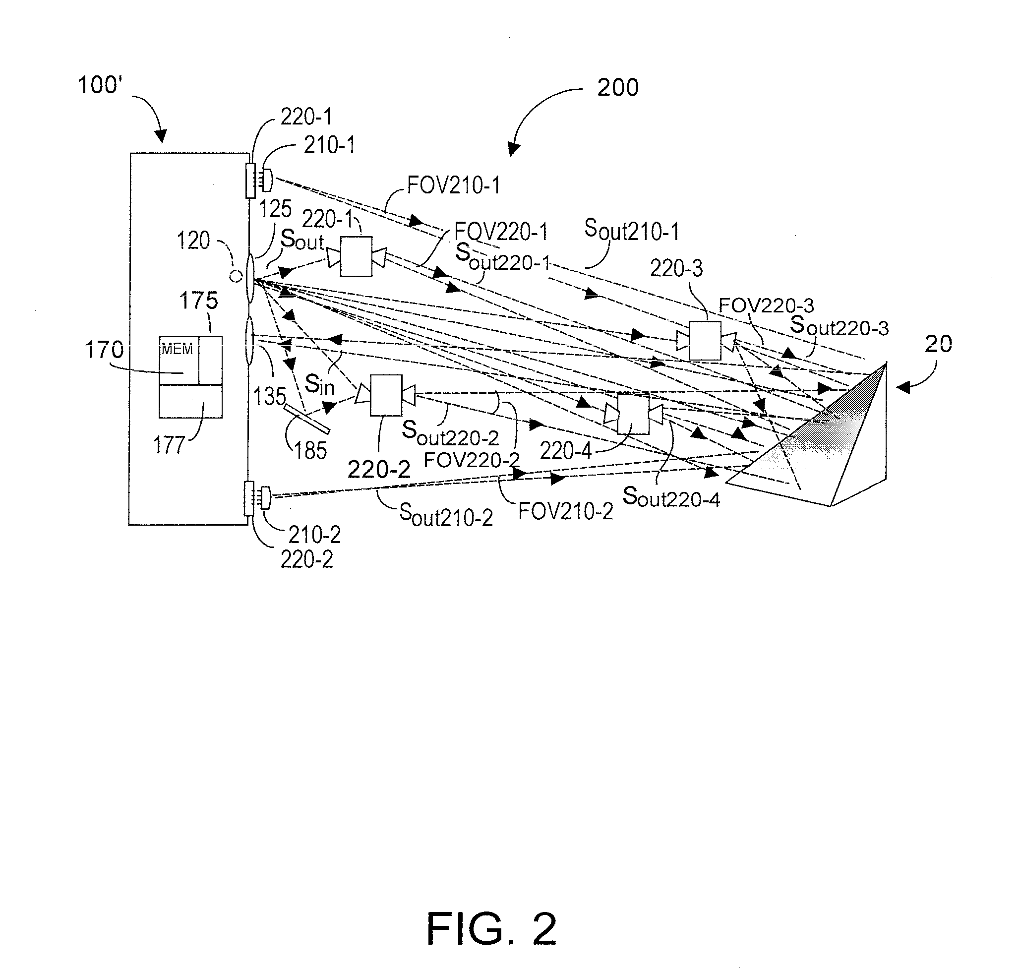
[0024]Quality and resolution of depth images and data acquired by a TOF system depends in part upon magnitude of the optical energy Sout emitted by the TOF system. As energy magnitude of Sout increases, effective Z range increases, and resolution of the acquired depth data at a given depth Z increases. In some applications, it may be desirable or necessary to increase effective Sout optical power illuminating only a portion of the target object. Magnitude of effective Sout optical power illumination varies inversely as the square of the distance Z separating the source of Sout and the target object. Thus one solution to increasing effective optical power is to reduce the distance Z. This can be accomplished by disposing at least one additional auxiliary optical energy unit (WOE) closer to the target object. The challenge, however, is to ensure that the frequency and phase of the emissions from each WOE are dynamically in synchronism with the frequency and phase of the TOF 100′ Sout ...


PUM


Abstract

TOF system optical power is augmented using auxiliary optical emitter unit(s) that may be a wireless (WOE), or a plug-wired (PWOE). WOE units sense emitted TOF system optical energy Sout and emit optical energy Sout-n preferably dynamically synchronized in frequency and in phase to Sout as received by the WOE. Each WOE includes at least one optical sensor to detect Sout, and internal feedback ensuring that frequency and phase of the WOE emitted Sout-n optical energy are dynamically synchronized with frequency and phase of the TOF emitted Sout optical energy. PWOE units need no internal feedback but are calibrated by the TOF system to cause a close match between frequency and phase of the PWOE-emitted optical energy with what would be emitted by the TOF system primary optical source. If PWOE(s) are used in isolation, delay difference between PWOE and the TOF primary optical energy source can be software-compensated.

Description

RELATION TO CO-PENDING APPLICATION[0001]Priority is claimed from co-pending U.S. provisional patent application Ser. No. 61 / 337,315, filed 1 Feb. 2010, entitled Multiple Synchronized Optical Sources for TOF Range Finding Systems.FIELD OF THE INVENTION[0002]The invention relates generally to phase-based time-of-flight (TOF) range finding systems, and more specifically to augmenting the source of optical energy used by such systems with at least one additional optical source that is dynamically frequency synchronized and phase synchronized to the source of primary optical energy. Such additional optical source(s) may be wirelessly located remote from the TOF system, or may be removably pluggably attachable to the TOF system itself.BACKGROUND OF THE INVENTION[0003]Time-of-flight (TOF) systems are known in the art, and include both non-phased based systems such as described in U.S. Pat. No. 6,323,942 “CMOS-Compatible Three-Dimensional Image Sensor IC” (2001), and phase-based systems suc...

Claims


Application Information

Patent Timeline
IPC IPC(8): G01C3/08G01S7/4911G01S17/894
CPCG01C3/08G01S17/36G01S7/4911G01S7/4815G01S17/89G01S17/894
Inventor BAMJI, CYRUS
Owner MICROSOFT TECH LICENSING LLC
Why Eureka
Try Eureka