Waveguide-Based Displays With Exit Pupil Expander

a display and waveguide technology, applied in the field of waveguide-based displays with exit pupil expanders, to achieve the effect of improving the optical performance of the display system

Active Publication Date: 2017-10-19
MICROSOFT TECH LICENSING LLC
View PDF1 Cites 137 Cited by
  • Summary
  • Abstract
  • Description
  • Claims
  • Application Information

AI Technical Summary

Benefits of technology

[0003]Certain embodiments described herein relate to a near eye or heads up display system that includes a scan beam projector, an optical waveguide, and an exit pupil expander (EPE). The EPE may be configured to expand an exit pupil associated with the scan beam projector prior to delivering a light beam from the scan beam projector to the optical waveguide. The exit pupil expander improves optical performance of the display system.

Problems solved by technology

As this is still an emerging technology, there are certain challenges associated with utilizing waveguides and / or other optical structures to display images of virtual objects to a user.

Method used


Image

  • Waveguide-Based Displays With Exit Pupil Expander
  • Waveguide-Based Displays With Exit Pupil Expander
  • Waveguide-Based Displays With Exit Pupil Expander

Examples


Embodiment Construction

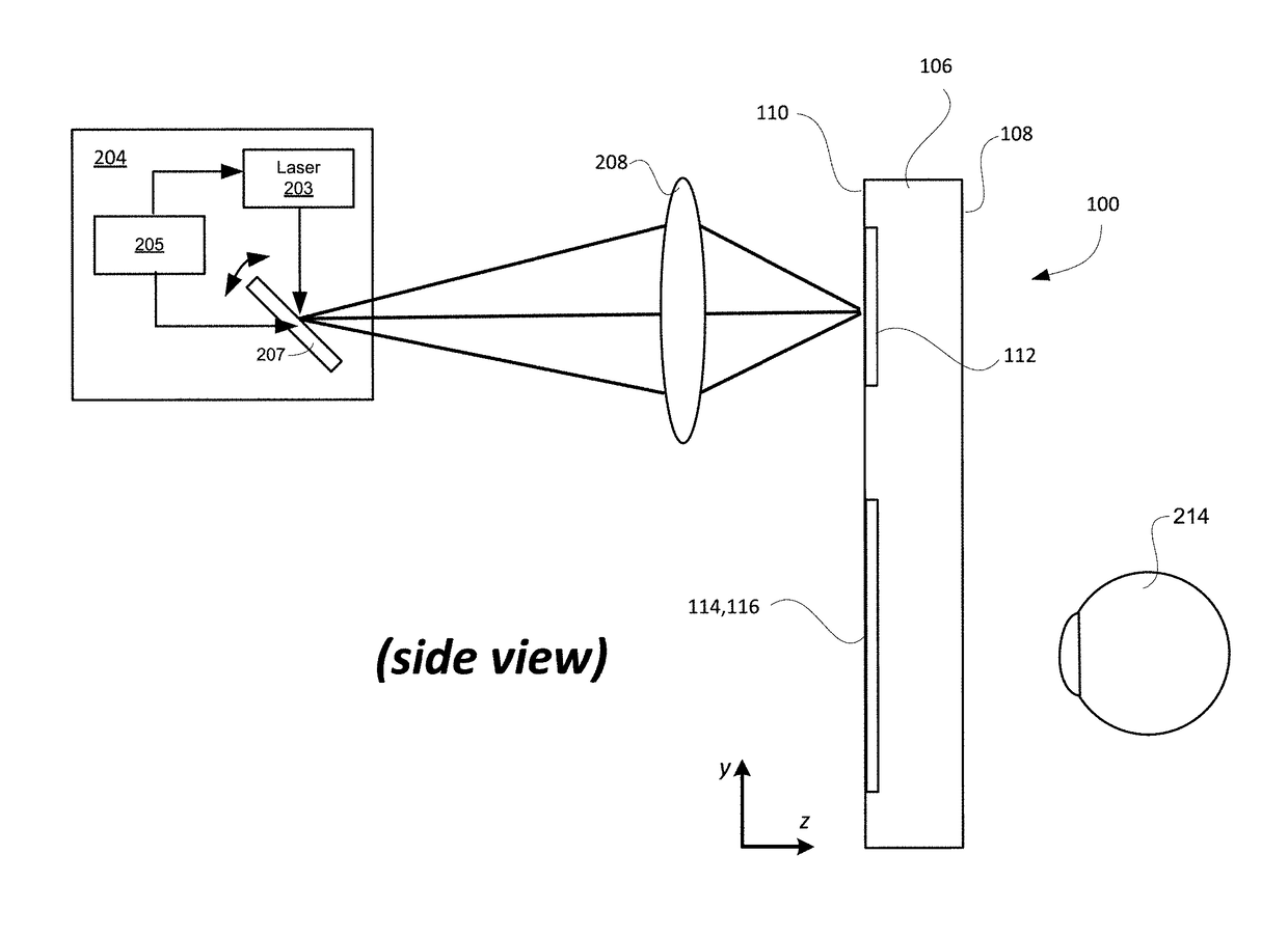
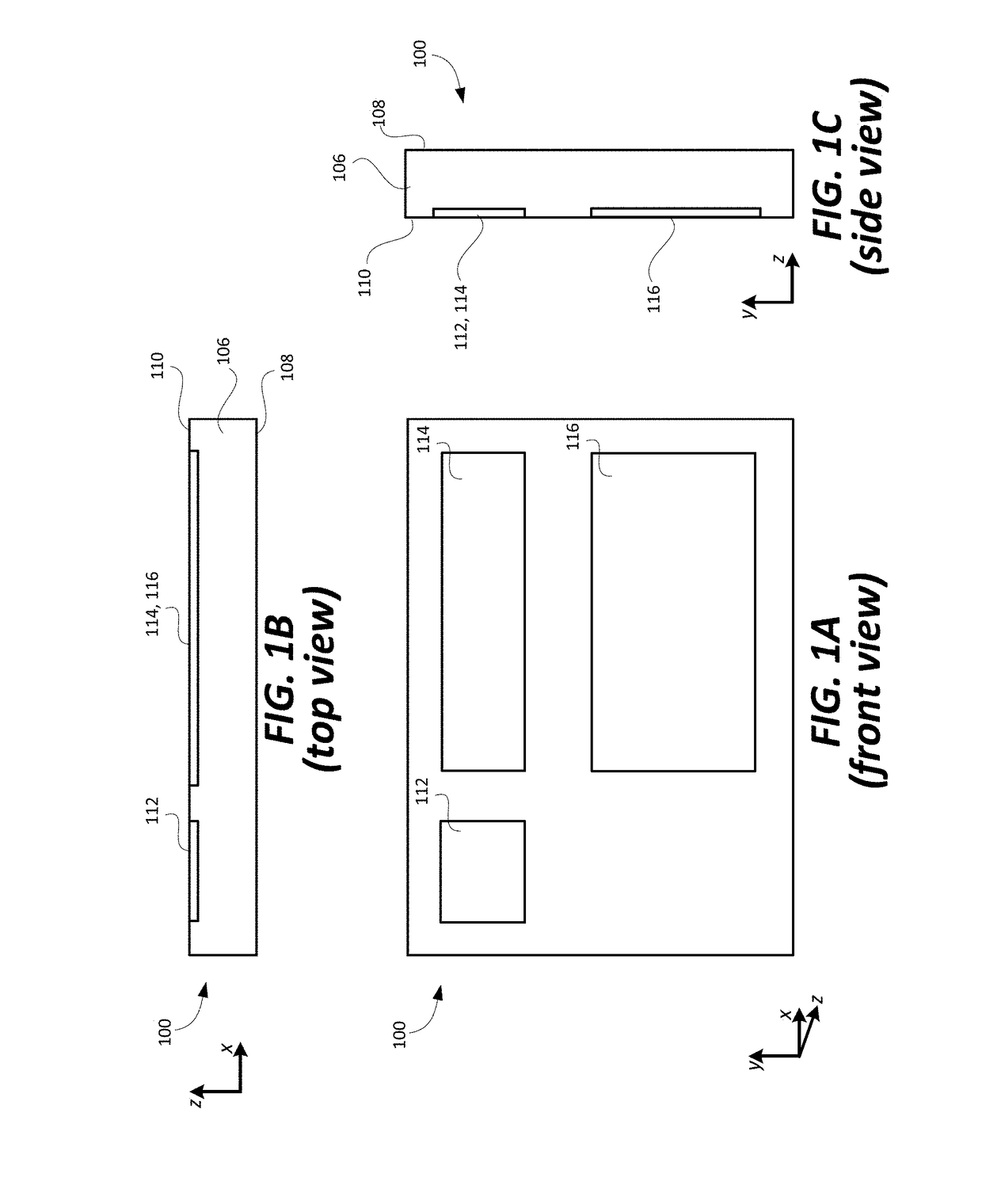
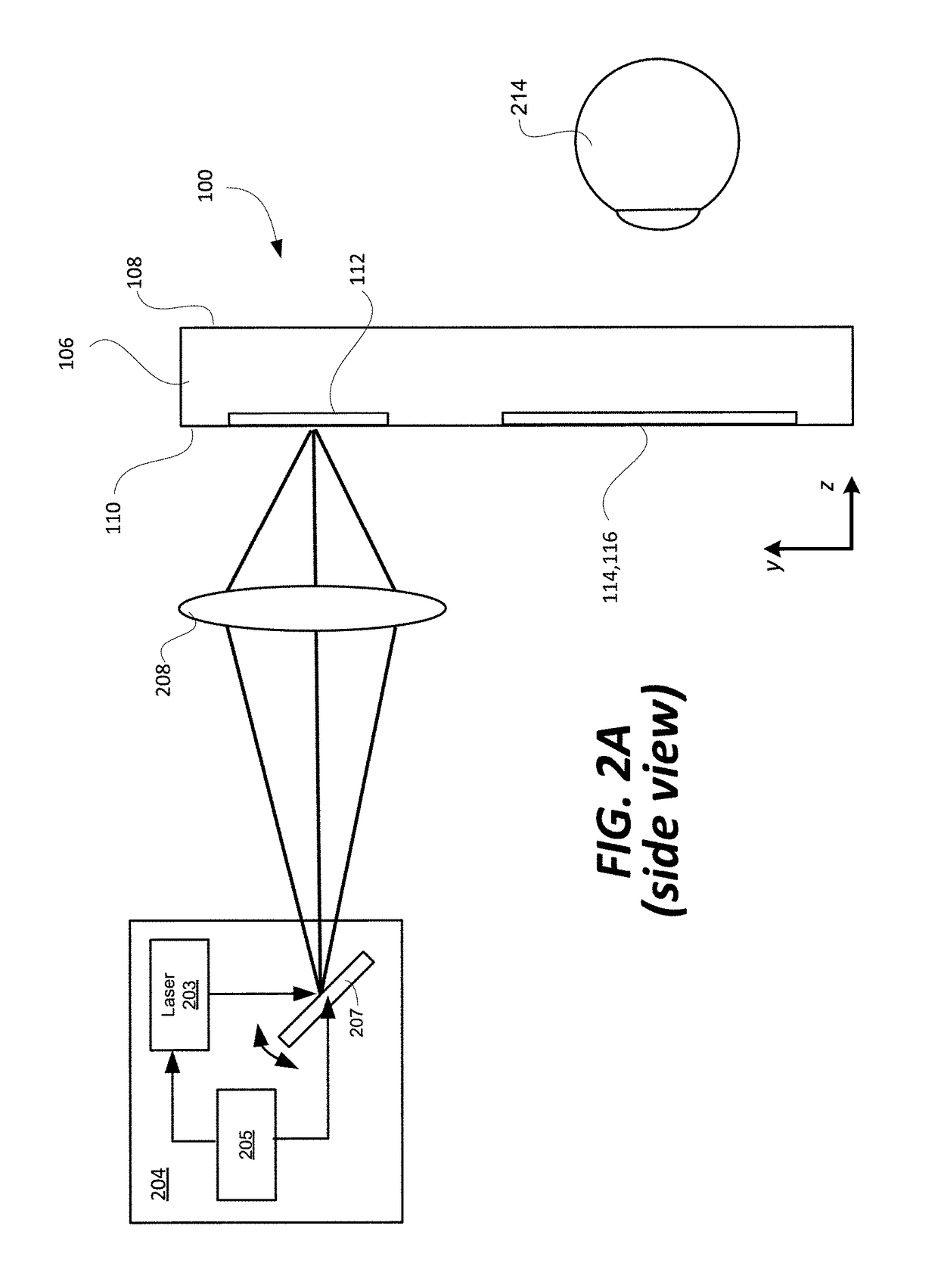
[0021]Certain embodiments of the present technology relate to a near eye or heads up display system that includes a scan beam projector, an exit pupil expander, and an optical waveguide. The exit pupil expander improves the optical performance of the display system.

[0022]Scan beam projectors (also known as light engines) are strong candidates for use in head mounted displays (HMD) due to their small size, low power requirements, and high brightness. It may be desirable to plane the scan beam projector pupil coincident at the entrance pupil of a waveguide or otherwise pupil replicating component. The conventional architecture of scan beam projectors, however, with a hermetically-sealed scan mirror for example, results in an internally-buried exit pupil that makes them hard to couple with other components that deliver the light to the user's eyes.

[0023]In addition, the mirror size in scan beam projectors is typically minimized to increase frame rate and scan angle, resulting in a smal...


PUM


Abstract

A near eye or heads up display system includes a scan beam projector engine, an optical waveguide, and an exit pupil expander (EPE) optically coupled between the scan beam projector engine and the optical waveguide. The EPE improves the optical performance of the display system. The EPE could include a diffusive optical element, diffractive optical element, micro-lens array (MLA), or relay of aspherical lenses. A dual MLA EPE may have cells that prevent cross-talk between adjacent pixels. A dual MLA EPE may have a non-periodic lens array. The optical power of one MLA may be different from the other MLA.

Description

BACKGROUND[0001]Various types of computing, entertainment, and / or mobile devices can be implemented with a transparent or semi-transparent display through which a user of a device can view the surrounding environment. Such devices, which can be referred to as see-through, mixed reality display device systems, or as augmented reality (AR) systems, enable a user to see through the transparent or semi-transparent display of a device to view the surrounding environment, and also see images of virtual objects (e.g., text, graphics, video, etc.) that are generated for display to appear as a part of, and / or overlaid upon, the surrounding environment.[0002]These devices, which can be implemented as head-mounted display (HMD) glasses or other wearable near eye display devices, or as a heads up display, but are not limited thereto, often utilize optical waveguides to replicate an image, e.g., produced by a display engine, to a location where a user of a device can view the image as a virtual ...

Claims


Application Information

Patent Timeline
Patent Type & Authority Applications(United States)
IPC IPC(8): G02B27/00G02B3/04G02B3/00F21V8/00G02B27/01
CPCG02B27/0081G02B27/0172G02B6/0026G02B2027/0118G02B3/0062G02B3/04G02B2027/0123G02B6/003G02B26/101G02B2027/0174G02B2027/0125
Inventor WALL, RICHARD ANDREWVALLIUS, TUOMASJUHOLA, MIKKO
Owner MICROSOFT TECH LICENSING LLC
Why Eureka
Try Eureka