Masked intraocular implants and lenses

a technology applied in the field of intraocular implants and lenses, can solve the problem that the ocular lens cannot be adapted to focus, and achieve the effect of reducing the tendency of the hole to produce visible diffraction

Active Publication Date: 2011-02-17
ACUFOCUS
View PDF119 Cites 133 Cited by
  • Summary
  • Abstract
  • Description
  • Claims
  • Application Information

AI Technical Summary

Benefits of technology

[0008]This application is directed to intraocular implants for improving the vision of a patient, such as by increasing the depth of focus of an eye of a patient. The intraocular implants can include a mask having an annular portion with a relatively low visible light transmission surrounding a relatively high transmission central portion such as a clear lens or aperture. This construct is adapted to provide an annular mask with a small aperture for light to pass through to the retina to increase depth of focus, sometimes referred to herein as pin-hole imaging or pin-hole vision correction. The intraocular implant may have an optical power for refractive correction. For example, the mask can be embodied in or combined with intraocular lenses (IOLs). The intraocular implant may be implanted in any location along the optical pathway in the eye, e.g., as an implant in the anterior or posterior chamber.
[0009]IOLs have been developed that provide a safe and effective surgical solution for cataracts. These lenses are surgically implanted after removal of a cataractous natural lens of the eye, restoring clarity and providing a replacement for the optical power that was removed. In a successful IOL implantation, the patient is typically emmetropic afterwards, meaning that their eye is focused for distance. However, conventional IOLs cannot accommodate to focus at different distances, so the patient typically needs additional correction (e.g., reading glasses) to see near objects clearly. Intraocular implants disclosed herein provide an improvement over presently available IOLs by incorporating a “mask” in the form of an aperture that improves depth of focus.
[0020]In certain embodiments, an intraocular implant includes an implant body comprising an outer surface that includes a posterior surface and an anterior surface, an opaque mask positioned between the posterior surface and the anterior surface of the implant body. The mask comprising an aperture. The intraocular implant can further include a support member coupled to the mask and extending from the mask to the outer surface of the implant body. The support member can extend from the mask to the posterior surface of the implant body. A first portion of the support member neighboring the mask can have a first cross-sectional area parallel the mask and a second portion of the support member neighboring the posterior surface can have a second cross-sectional area parallel the mask that is less than the first cross-sectional area. The support member may be configured to be removable from the intraocular implant. The support member may include a plurality of holes characterized in that at least one of the hole size, shape, orientation, and spacing of the plurality of holes is varied to reduce the tendency of the holes to produce visible diffraction patterns.
[0024]In another embodiment, a method of making an intraocular implant includes providing an optic with an annular cavity around an aperture region, at least partially filling the cavity with an opaque material, removing at least some of the aperture region and a central region of the optic to reduce a thickness of the aperture region of the optic. At least some of the opaque material can remain on the surface of the optic to form an opaque mask.
[0026]In certain embodiments, a intraocular implant includes an implant body comprising a body material and a mask with an aperture positioned within the implant body. The mask can include a plurality of holes that extend between a posterior surface and an anterior surface of the mask. The body material can extend through the plurality of holes of the mask, and the plurality of holes can be characterized in that at least one of the hole size, shape, orientation, and spacing of the plurality of holes is varied to reduce the tendency of the holes to produce visible diffraction patterns. The plurality of holes may be positioned at irregular locations. A first plurality of the holes may include first hole size, shape or spacing and at least another plurality of holes may include a second hole size, shape, or spacing different from the first holes size, shape, or spacing. A first plurality of the holes may include first hole size, a second plurality of the holes may include a second hole size different from the third hole size, and a third plurality of holes may include a third hole size different from the first holes size and the second hole size.

Problems solved by technology

However, conventional IOLs cannot accommodate to focus at different distances, so the patient typically needs additional correction (e.g., reading glasses) to see near objects clearly.

Method used


Image

  • Masked intraocular implants and lenses
  • Masked intraocular implants and lenses
  • Masked intraocular implants and lenses

Examples


Embodiment Construction

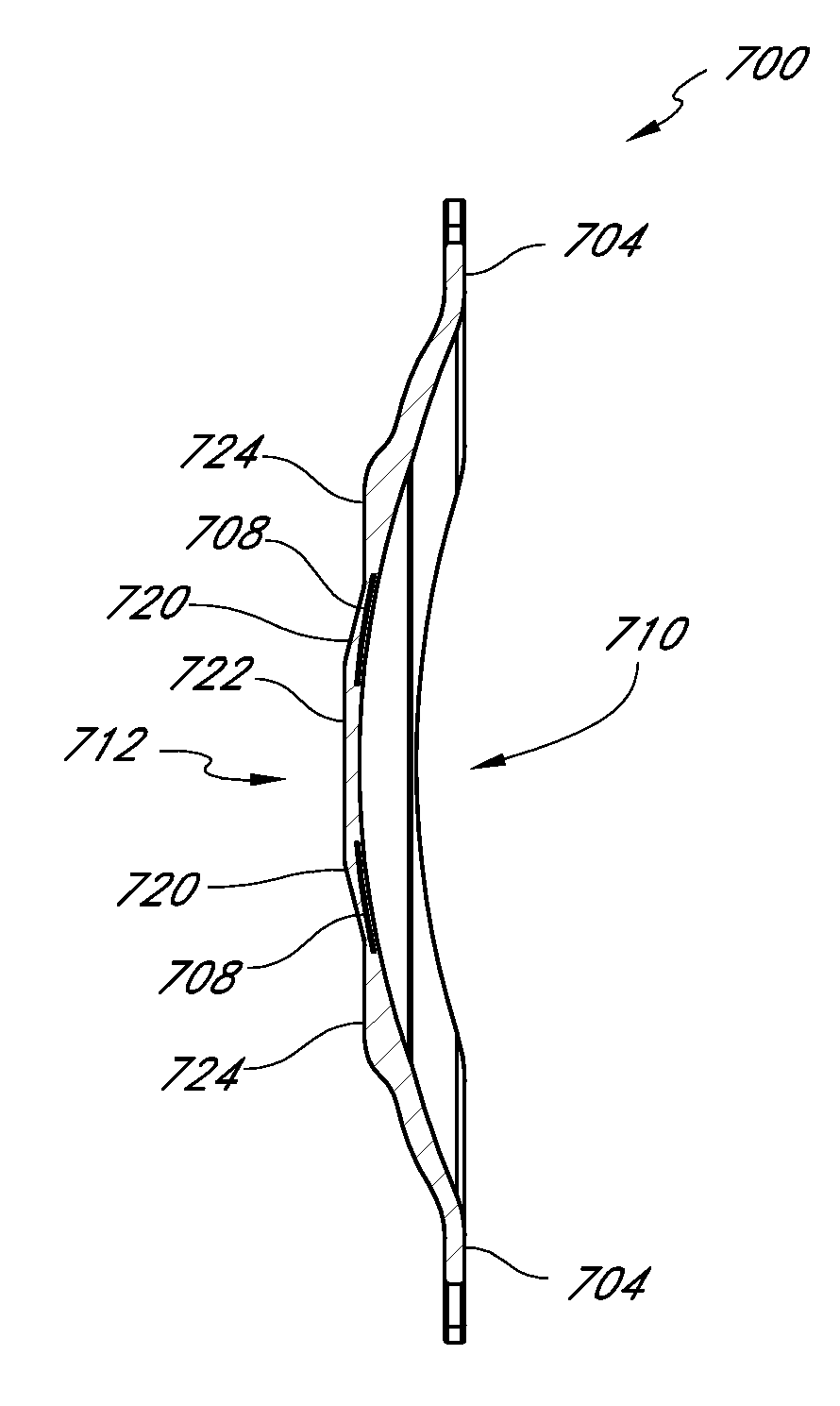
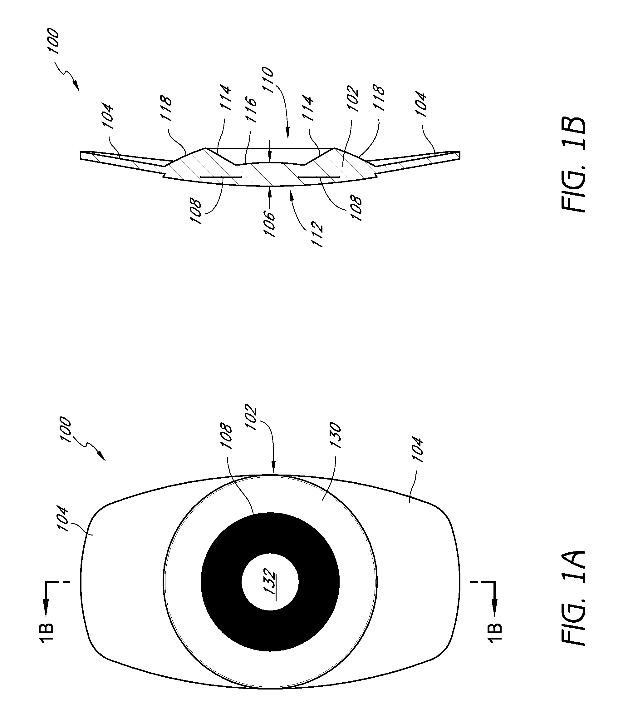
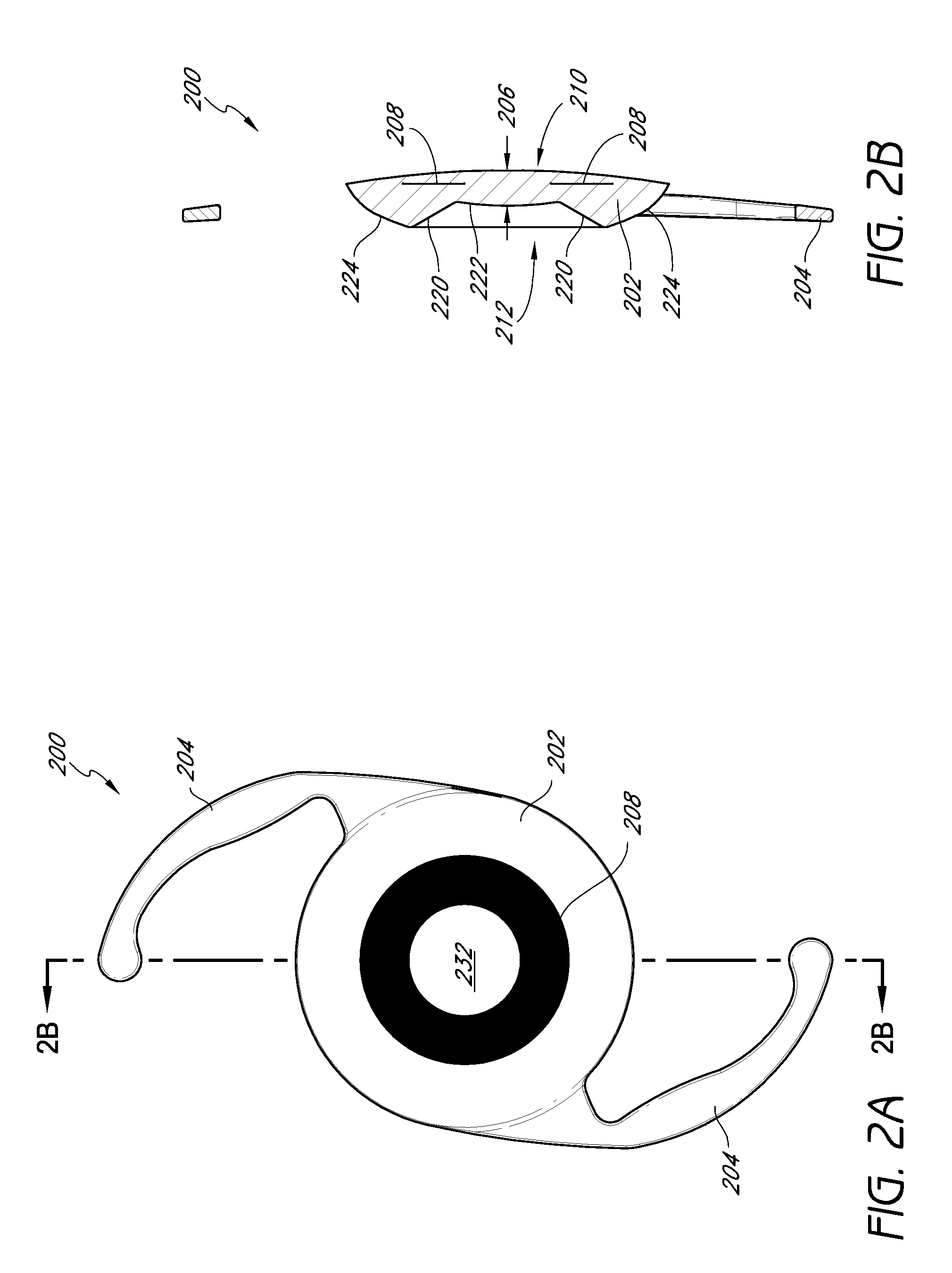
[0147]This application is directed to intraocular implants and methods of implanting intraocular implants. The natural lens of an eye is often replaced with an intraocular lens when the natural lens has been clouded over by a cataract. An intraocular lens may also be implanted into the eye to correct other refractive defects without removing the natural lens. The intraocular implants of the preferred embodiments include a mask adapted to provide a small aperture for light to pass through to the retina to increase depth of focus, sometimes referred to herein as pinhole imaging or pinhole vision correction. The intraocular implants may be implanted in the anterior chamber or the posterior chamber of the eye. In the posterior chamber, the implants may be fixated in the ciliary sulcus, in the capsular bag, or anywhere an intraocular implant is fixated. In some embodiments discussed below, the intraocular lenses have a reduced thickness in a central region compared to conventional intrao...


PUM

PropertyMeasurementUnit
diameteraaaaaaaaaa
outer diameteraaaaaaaaaa
diameteraaaaaaaaaa

Abstract

Intraocular implants and methods of making intraocular implants are provided. The intraocular implants can improve the vision of a patient, such as by increasing the depth of focus of an eye of a patient. In particular, the intraocular implants can include a mask having an annular portion with a relatively low visible light transmission surrounding a relatively high transmission central portion such as a clear lens or aperture. This construct is adapted to provide an annular mask with a small aperture for light to pass through to the retina to increase depth of focus. The intraocular implant may have an optical power for refractive correction. The intraocular implant may be implanted in any location along the optical pathway in the eye, e.g., as an implant in the anterior or posterior chamber.

Description

CROSS-REFERENCE TO RELATED APPLICATIONS[0001]This application claims the benefit of U.S. Provisional Application Nos. 61 / 233,794, filed Aug. 13, 2009, and 61 / 233,804, filed Aug. 13, 2009, the entirety of each of which is hereby incorporated by reference.BACKGROUND[0002]1. Field[0003]This application relates generally to the field of intraocular devices. More particularly, this application is directed to intraocular implants and lenses (IOLs), with an aperture to increase depth of focus (e.g. “masked” intraocular lenses) and methods of making.[0004]2. Description of the Related Art[0005]The human eye functions to provide vision by transmitting and focusing light through a clear outer portion called the cornea, and further refining the focus of the image by way of a crystalline lens onto a retina. The quality of the focused image depends on many factors including the size and shape of the eye, and the transparency of the cornea and the lens.[0006]The optical power of the eye is determ...

Claims


Application Information

Patent Timeline
Patent Type & Authority Applications(United States)
IPC IPC(8): A61F2/16
CPCA61F2/1613A61F2/1659A61F2250/0098A61F2210/0076A61F2250/0053A61F2250/0058A61F2/16B29D11/023A61F2002/1696A61F2/15A61F2002/1681A61F2240/002B29D11/00317A61F2/14B29K2033/04B29K2105/0085
Inventor CHRISTIE, BRUCE A.KOSMYNINE, ALEXEI N.
Owner ACUFOCUS
Why Eureka
Try Eureka