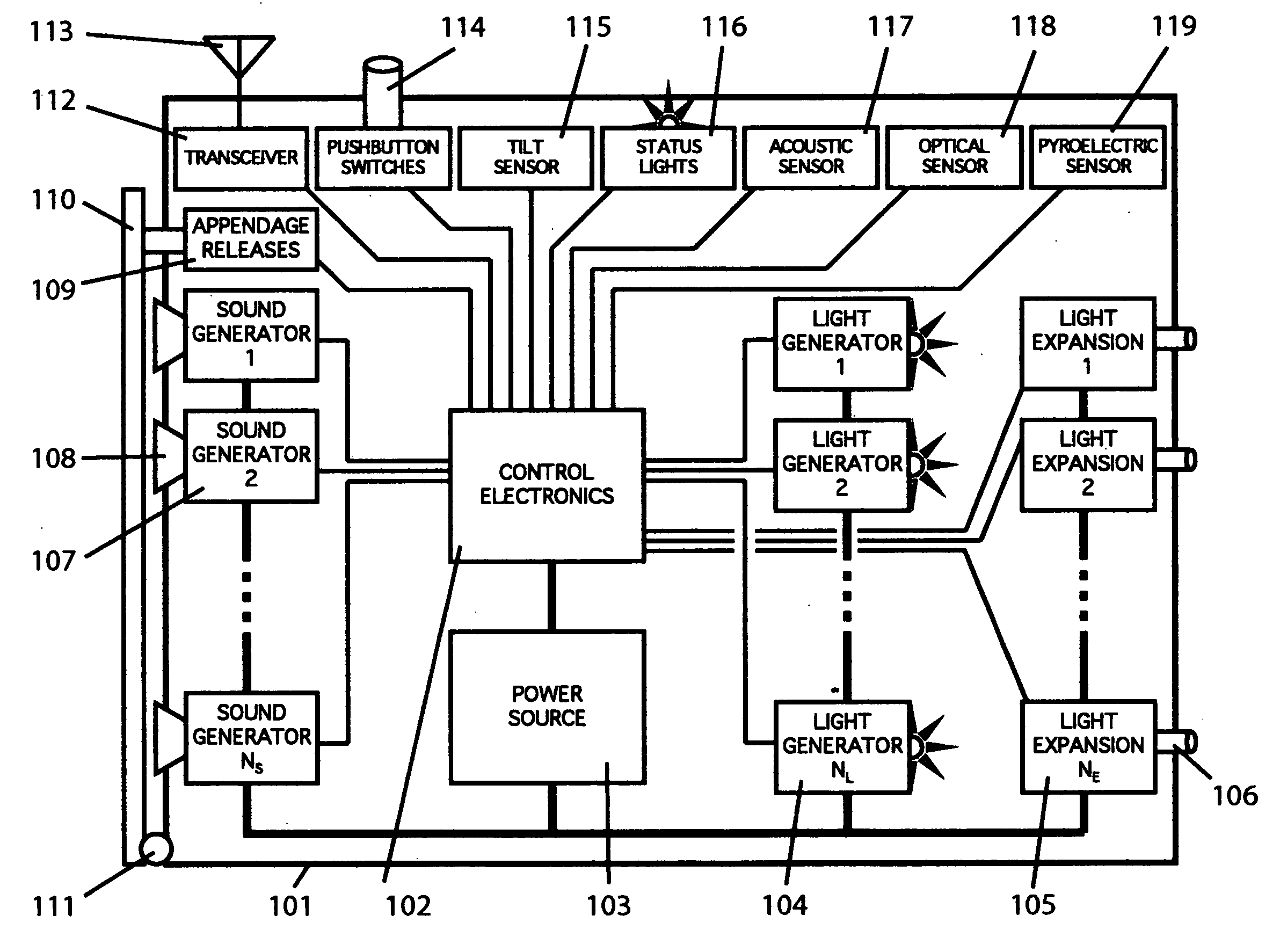
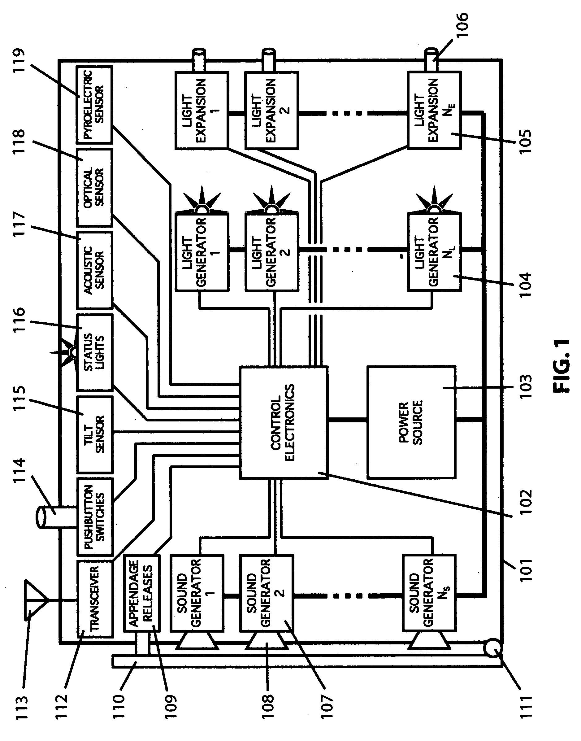
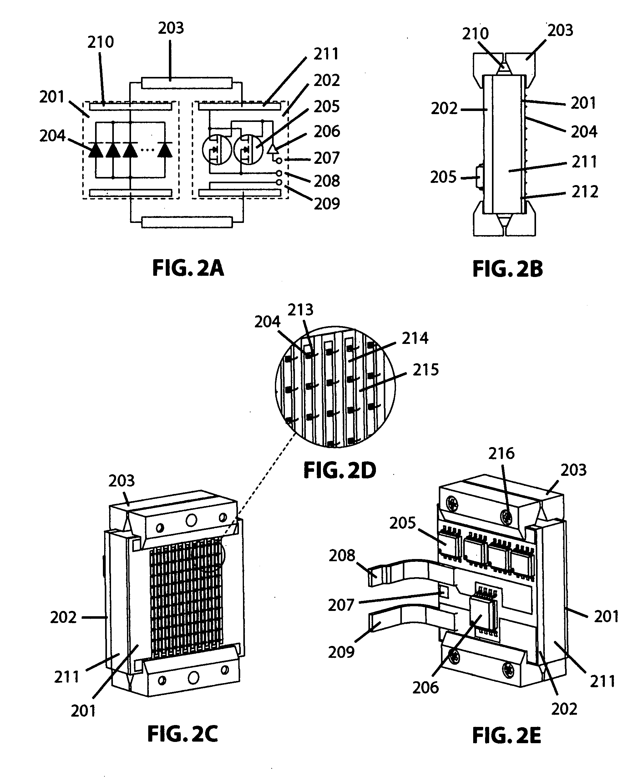
[0021]The
projectile's
light source may be comprised of one or more modules each containing an array of light-emitting diodes (LEDs) operating at a center
wavelength in the range from 350 nm to 980 nm, but preferably from 510 nm to 550 nm (an array may consist of one light-emitting
diode). The
light source modules in this embodiment combine the functions of
electrical switching of the
supply current, delivery of current to the plurality of LEDs, and
thermal conduction of
waste heat to an appropriate sink, all within a compact mechanical
package. The
light source modules are specifically engineered to provide an optimum areal density of LED emitters and good
thermal conductivity to an adequate
heat sink. To achieve this, one or more unpackaged LED dice are bonded directly to an electrical substrate with high
thermal conductivity, and contain a wire bond to another
electrode to complete the LEDs electrical circuit. The electrical substrate is subsequently attached to a
heat sink with a very low
thermal resistance bond. With this practice, large amounts of radiant power can be emitted by the LEDs without damage or
wavelength shift due to the temperature increase in the LED junction. In addition to good
thermal control, the use of bare LED dice increases efficiency of the light output, and projects light over a wider
angular distribution than if commercial
LED packaging were being used.
[0022]The absence of the plastic lens found on most commercial LEDs allows the LED die to emit in a cone with 120° full angle. Therefore a single light generation module populated with LED dice also has an emission full angle of approximately 120°. This angle is sufficiently large that two to three light generation modules are sufficient to completely illuminate all parts of a room, providing disorienting effects to all occupants of the room.
[0027]The
projectile may contain a means for dispersal of a cloud of diffusely reflecting material, the function of which is to increase the
effective size of the light generator source. It is well known that obstruction of an
adversary's field of vision is increased as the size of the light source is increased. A variant of this embodiment contains a means for inflating a thin diffusely reflecting membrane, from which light from the light generation source reflects, causing an increase in the
effective size of the light source.
[0031]The
projectile and its components may be housed in a rugged housing that provides mounting fixtures and protection to internal components. In this embodiment, the projectile can be launched by hand or by mechanical or pyrotechnic propulsion means to cause the projectile to travel a desired distance. In this embodiment, there is a selectable
delay time built into the optical and audio sequencing of the
software programs to compensate for the projectile
flight time between activation and arrival at the target. The rugged case provides for protection of internal components, and is transparent in the spatial location of each light generating module to the part of the
electromagnetic spectrum emitted by the light generating module. Typical shapes that facilitate hand throwing or launching include cylinders, spheres, and ovoids.
[0033]Radio-frequency transceivers connected to the projectile's control circuitry may allow a plurality of projectiles in the same general vicinity of one another to synchronize their respective
software programs, and thus to activate their respective light generation and
sound generation modules in such a fashion that the collective effect is optimized for disorientation or
confusion of adversaries. One aspect of this embodiment is that deploying personnel may be provided with
protective gear (
eyewear, acoustic attenuators, etc.) that also synchronize with the radio-frequency signals, and so provide a measure of protection against the effects of the projectiles.
[0034]A non-lethal projectile that is capable of producing flashblindness or glare in an
adversary has value for law-
enforcement operations, hostage-rescue operations, military operations, prison inmate control applications, and in surprise raids on alleged criminals or criminal activity. It follows that, because the projectile can be used safely against any personnel, the projectile has application in the training of law
enforcement, special operations, and military personnel, without any danger of damage to human eyesight, hearing, or training infrastructure. Similarly, the non-lethal projectile has direct application in simulated warfare for entertainment, or paintball games. In paintball, lethal weapons have simulants that fire small frangible
pellets containing a
colored paint or other marker. Participants in the game are “killed” when marked by the paint, and must immediately leave the game. Larger-
caliber weapons are simulated by firing spongy plastic projectiles at vehicles or buildings. In this case, in the absence of a paint marker, a field judge or referee will typically decide when structural damage or player casualties result. There is a large and growing market for guns, rifles, and other paraphernalia associated with the game of paintball. The non-lethal projectile is an ideal addition to the paintball player's arsenal for all of the same reasons that it is of use to law enforcement and military users. A paintball player could use the non-lethal projectile to temporarily disorient or confuse simulated adversaries in an enclosed environment, providing additional surprise and time to fire paint-filled
pellets at the occupants. Alternately, the non-lethal projectile could be used as a throwable grenade simulant, in which case a judge or referee would rule players out of the game if within a predetermined
radius of the projectile when it was activated. A paint-filled
balloon is presently used as a grenade simulant, but does not have the range or reuseability that the present invention would provide. In another application, the non-lethal projectile could be used as a simulated bomb or mine, which could be “defused” or rendered harmless by actuating a plurality of pushbuttons in a correct sequence. Unless the sequence entered is one of the (possibly multiple) correct sequences, the device activates immediately, or after a time
delay. A judge or referee would then determine the simulated
lethality of the device to players, nearby vehicles, or buildings. Variations of this device might contain
motion sensors, proximity sensors, or acoustic sensors that could be used to activate the device.


