Projector with a projection position adjusting device

a projection position and adjustment device technology, applied in the field of projection devices, can solve the problems of difficult to realize a reduction in the size and weight of the projection position adjustment device, the size of the pressing member and the size of the coupling through hole is extremely large, and achieves the effect of improving convenience and facilitating replacemen

Inactive Publication Date: 2011-10-18
SEIKO EPSON CORP
View PDF4 Cites 7 Cited by
  • Summary
  • Abstract
  • Description
  • Claims
  • Application Information

AI Technical Summary

Benefits of technology

[0010]An advantage of some aspect of the invention is to provide a projector that can stably maintain focus accuracy of a projected image even when a projection position is adjusted and can realize a reduction in size and weight.
[0014]As explained above, according to the aspect of the invention, it is possible to omit the auxiliary plate and the plural urging members in the past and reduce the number of components and to realize a reduction in size and weight of the projection position adjusting device.
[0015]Moreover, because the first moving plate is brought into contact with the fixed member by the plural coupling members, it is possible to prevent backlash of the first moving plate (backlash of the projection optical device supported by the first moving plate). Even when the projection optical device is moved by the projection position adjusting device, it is possible to prevent shift of a back focus position of the projection optical device and stably maintain focus accuracy of a projected image projected from the projector.
[0022]Because the pressing member includes the two pressing members, i.e., the first pressing member and the second pressing member, compared with the pressing member including only one member, it is possible to form the pressing member and the coupling through hole relatively small and realize a reduction in size of the projection position adjusting device.
[0024]In the aspect of the invention, the connecting member has the pair of flat surfaces orthogonal to the up to down direction on the outer surface thereof. The pair of flat surfaces come into slide contact with the first through hole. Consequently, when the first moving plate moves in the up to down direction, the first pressing member is prevented from rotating in the plane orthogonal to the projecting direction by the pair of flat surfaces. It is possible to move the first pressing member in the up to down direction together with the first moving plate. Therefore, when the first moving plate moves in the up to down direction, the first pressing member does not rotate and slip out of the step. It is possible to maintain a state of attachment of the first moving plate to the fixed member satisfactory.
[0026]In the aspect of the invention, in the projection position adjusting device, the first moving plate is disposed on the projecting direction side with respect to the fixed member. The other members such as the second moving plate and the fixed member are not present on the projecting direction side of the first moving plate. Consequently, it is possible to adopt a configuration in which the projection optical device is detachably mountable on the first moving plate from the projecting direction side. When such a configuration is adopted, it is possible to easily carry out replacement of the projection optical device and realize improvement of convenience.

Problems solved by technology

Therefore, because a large number of members are used, it is difficult to realize a reduction in size and weight of the projection position adjusting device.
Therefore, the pressing member and the coupling through hole need to be formed relatively large and it is difficult to realize a reduction in size of the projection position adjusting device.
In particular, when the moving range in the axial direction of the first moving plate is set large, the size of the pressing member and the size of the coupling through hole are extremely large.

Method used


Image

  • Projector with a projection position adjusting device
  • Projector with a projection position adjusting device
  • Projector with a projection position adjusting device

Examples


Embodiment Construction

[0045]An embodiment of the invention is explained below with reference to the accompanying drawings.

External Structure

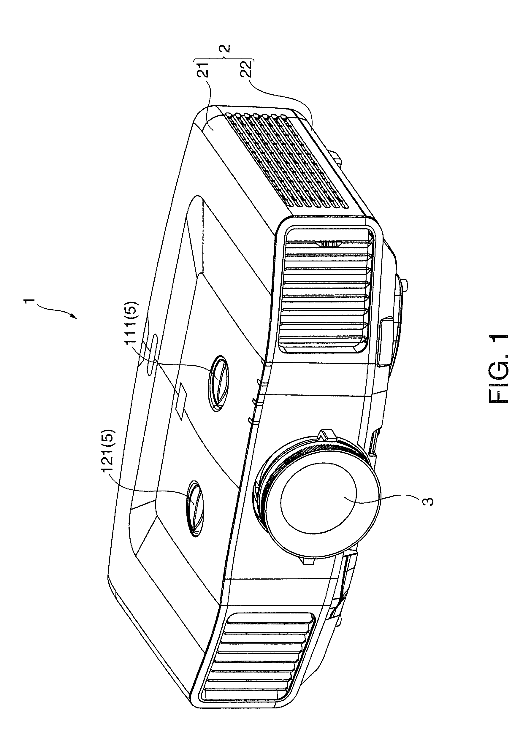
[0046]FIG. 1 is a perspective view of an external appearance of a projector 1 according to this embodiment. Specifically, FIG. 1 is a perspective view of the projector 1 set on a desk or the like viewed from the front upper side.

[0047]“Up”, “down”, “left”, and “right” described below correspond to up, down, the left, and the right in the view shown in FIG. 1. “Front” and “back” described below correspond to the front and the back in the view shown in FIG. 1.

[0048]The projector 1 modulates, according to image information, a light beam emitted from a light source, forms image light, and magnifies and projects the formed image light on a screen (not shown). As shown in FIG. 1, the projector 1 includes an armor housing 2 that configures an armor.

[0049]The armor housing 2 houses an apparatus main body of the projector 1. As shown in FIG. 1, the armor housing 2 includes an...


PUM


Abstract

A projector includes a projection optical device and a projection position adjusting device that includes a fixed member defining a hole having a step portion, a first plate that supports the projection optical device and a second plate disposed between the fixed member and the first plate. The projection position adjusting device further includes a connecting member having a step and being disposed in the hole of the fixed member and connected to the first plate, and an urging member disposed between the connecting member and the step portion of the hole of the fixed member. The urging member urges the step portion of the hole and the step of the connecting member away from each other, and urges the first plate into direct contact with the fixed member.

Description

[0001]This application claims priority to Japanese Application No. JP 2008-012939 filed in Japan on Jan. 23, 2008, the entire disclosure of which is hereby incorporated by reference in its entirety.BACKGROUND[0002]1. Technical Field[0003]The present invention relates to a projector.[0004]2. Related Art[0005]There is known a projector that modulates, according to image information, a light beam emitted from a light source and magnifies and projects the light beam on a screen using a projection optical device.[0006]In such a projector, the light beam is tilt-projected upward with the projector fixed in a low position, tilt-projected downward with the projector fixed in a high position, and, besides the projection in the vertical direction, tilt-projected in the horizontal direction. Therefore, there is known a projector including a projection position adjusting device that moves, with respect to an optical system such as an optical modulation device, a projection optical device in a d...

Claims


Application Information

Patent Timeline
Patent Type & Authority Patents(United States)
IPC IPC(8): G03B21/14G03B21/22
CPCG03B27/62
Inventor KITAHARA, WATARUNAKAMURA, KUNIHISAKURIHARA, TORU
Owner SEIKO EPSON CORP
Why Eureka
Try Eureka