Contouring toothbrush head

a technology of tooth brush and head, which is applied in the field of tooth brush, can solve the problems of premature splaying of the bristles, the inability to properly clean the tooth brush, etc., and achieves the effect of reducing manufacturing costs and inherent gentleness on the gums

Inactive Publication Date: 2006-06-08
HOHLBEIN DOUGLAS J
View PDF5 Cites 62 Cited by
  • Summary
  • Abstract
  • Description
  • Claims
  • Application Information

AI Technical Summary

Benefits of technology

[0007] An advantage of the present flexible configuration is, in addition to the above noted features of a curved configuration, its inherent gentleness on the gums. When one brushes along the gumline with a power tip configuration, one focuses much of the force through the concentrated area at the raised tip. With the present configuration, this force is more evenly distributed.
[0008] There are considerable manufacturing efficiencies with having the elastomer material of this invention used in the flex area being the same elastic material as that which may be used as a grip material in the handle area. Therefore, a configuration which allows flexing under the loads typically encountered during brushing with materials which are suitable for use as a grip would be desirable.
[0009] To achieve the flexibility described above, the cross section of elastomer may be convoluted, with one or more convolutes. To aid in fixing the elastomer to the toothbrush head sections, the elastomer may be configured to fit into one or more slots at both ends of the flexing area.
[0010] To minimize the gap between bristle tufts when the head is flexed into a flat configuration, it is desirable to position the plastic (resin) bridge between the tip and handle portions as near the bristle tips as possible. This bridge is straightened during flexing, and directly controls the gap between bristle tufts on each side of the flex area.

Problems solved by technology

Many current brushes which have rigidly mounted bristles and a rigid curved / angled bristle surface exhibit an inherent disadvantage when brushing both flat as well as concave tooth surfaces.
These fewer bristles must support the brushing forces applied through the handle, which will result in premature splaying of the bristles.

Method used


Image

  • Contouring toothbrush head
  • Contouring toothbrush head
  • Contouring toothbrush head

Examples


second embodiment

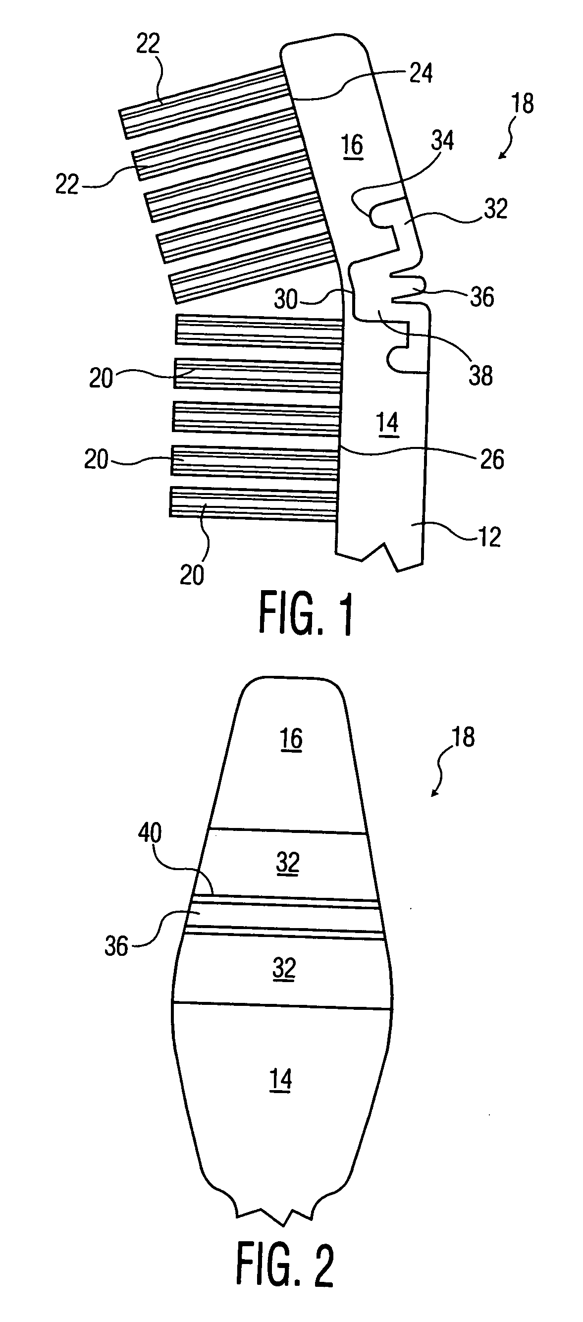
[0036]FIG. 4 illustrates the invention, there shown as horizontally disposed, and similar to that of FIGS. 1 and 2 except for a different construction for angularly joining the two head sections. The elastomer joint is again denoted as 18, with the elastomer itself denoted as 50 and being of the same composition as previously set out, and extends across the width of the head, and is located between the facing ends of sections 14 and 16. A thin integral bridge connection centrally between the two sections is designated as 52, typically being of cylindrical form in transverse cross section. Each end is integral with a respective head section. The elastomer is seen as completely surrounding bridge 52. This bridge connection may be, in transverse cross section, of any desired form. A top plan view of the head would be similar to FIG. 2, except for the absence of grooves 40 and rib 36. As seen at FIG. 4, the extent of the elastomer along the toothbrush longitudinal axis is shorter than t...

third embodiment

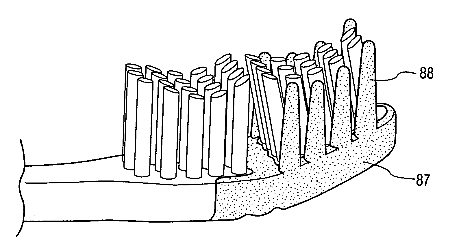
[0037]FIG. 5 shows a third embodiment, again shown as horizontal. There, the lower surfaces 24 and 26 of bristled head sections 14 and 16 are joined by an intermediate arcuate bottom surface 27 having tufts of bristles 23 extending orthogonally and downwardly therefrom. An elastomer section 18 is generally C shaped and has a bight part 60 and tips or ends 62, the latter located in respective complementary double troughs or double grooves which extend transversely across the head. The elastomer tips are separated by head portion 64, with thin bridges 66, again formed from the molded resin forming the toothbrush, joining the two head sections at the lower surface of the whole head. The C shaped elastomer thus surrounds portion 64 across the width of the head.

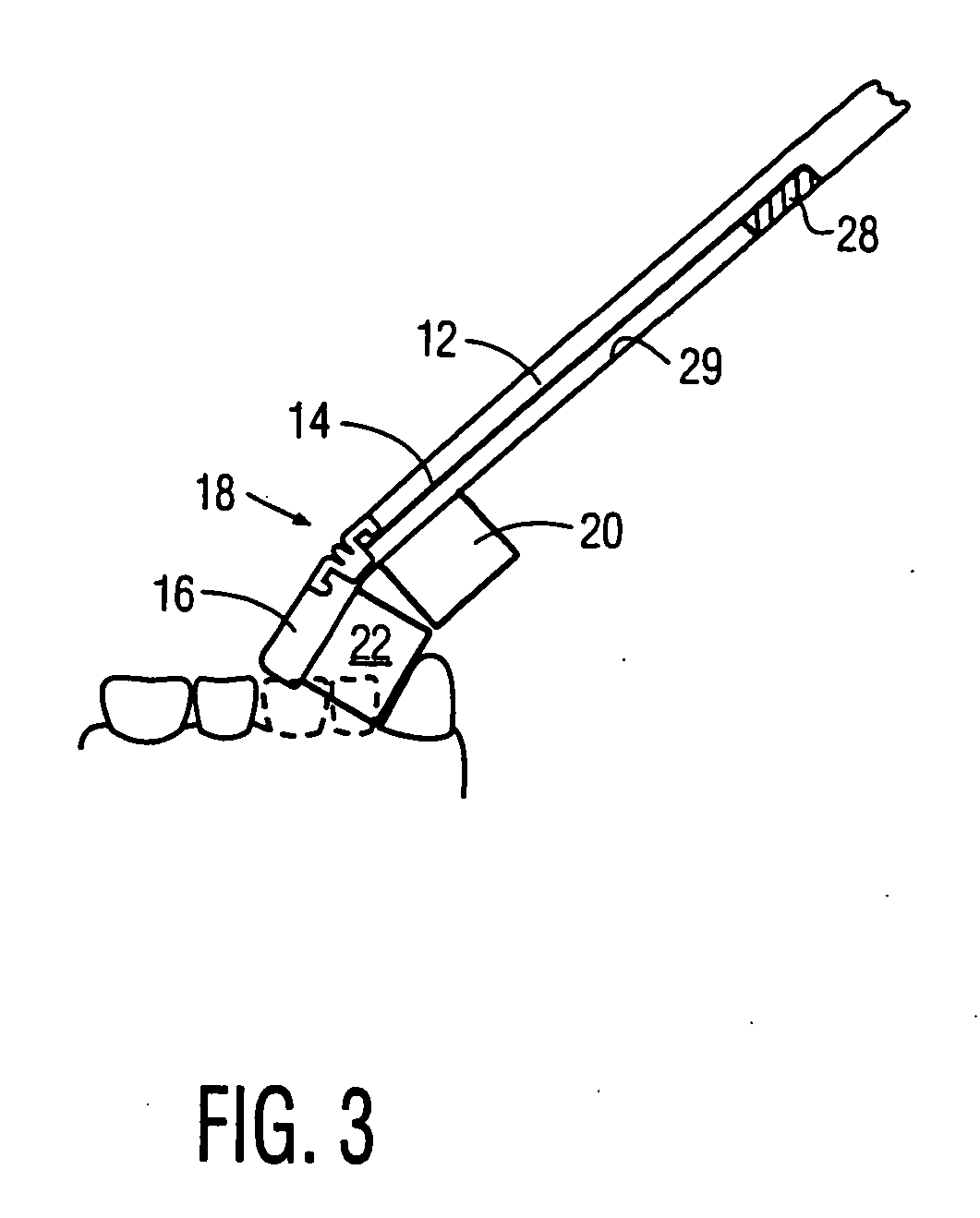
[0038] The second and third embodiments yield the same cleaning action as shown at FIG. 3. The thickness of bridges 52 and 66 is the same as that of bridge 30 of FIG. 1.

[0039] It is seen that the bridges 30, 52 and 66 of the resp...

fourth embodiment

[0040]FIG. 6 illustrates a fourth embodiment which differs from that shown in FIG. 1 only in the absence of bridge 30, of FIG. 1. Instead of bridge 30, the two head sections are coupled by T shaped elastomer section 39, the latter being of the same form as that of section 38 of FIG. 1, except that it extends all the way to the lower surface of the head.


PUM


Abstract

The present invention discloses a toothbrush having a handle and an articulated head coupled to the handle. The articulated head includes two sections and each of the head sections has a bottom surface and a side surface. Each of the head sections includes a plurality of bristles extending from the bottom surface of that head section and at least one of the head sections includes a plurality of elastomeric fingers partially defining the side surface of that head section and partially extending from the bottom surface of the head section. The head section most remote from the handle, in a normal configuration of the articulated head, is angled with respect to the other head section.

Description

CROSS-REFERENCE TO RELATED APPICATIONS [0001] This application is a Continuation Application of U.S. patent application Ser. No. 10 / 109,637, filed Apr. 1, 2002, which is a Continuation-in-part of U.S. patent application Ser. No. 29 / 148,074, filed Sep. 14, 2001 (now U.S. Pat. No. D456,139S) and of U.S. patent application Ser. No. 09 / 897,606, filed Jul. 3, 2001. U.S. patent application Ser. No. 09 / 897,606 is a Continuation Application of U.S. patent application Ser. No. 09 / 422,953, filed Oct. 22, 1999 (now U.S. Pat. No. 6,314,606), which is a Continuation Application of U.S. patent application Ser. No. 09 / 351,178, filed Jul. 12, 1999 (now U.S. Pat. No. 6,073,299), which is a Continuation Application of U.S. application Ser. No. 09 / 090,331, filed May 29, 1998 (now U.S. Pat. No. 5,991,958), which is a Continuation Application of U.S. patent application Ser. No. 08 / 762,783, filed Dec. 10, 1996 (now U.S. Pat. No. 5,758,393), which claims priority under 35 U.S.C. § 119(e) of Provisional Pa...

Claims


Application Information

Patent Timeline
Patent Type & Authority Applications(United States)
IPC IPC(8): A46B9/04A46B7/02A46B7/06
CPCA46B5/002A46B5/0025A46B7/06A46B9/026A46B9/028B29L2031/425A46B9/045A46B15/0002A46B15/0032A46B2200/1066A46B9/04
Inventor HOHLBEIN, DOUGLAS J.
Owner HOHLBEIN DOUGLAS J
Why Eureka
Try Eureka