
Carton with dispenser

a dispenser and carton technology, applied in the field of cartons, can solve the problem that users can have difficulty in grasping the articles furthest from the dispenser

Inactive Publication Date: 2006-06-08
MEADWESTVACO PACKAGING SYST LLC
View PDF13 Cites 73 Cited by
  • Summary
  • Abstract
  • Description
  • Claims
  • Application Information

AI Technical Summary

Benefits of technology

[0011] The articles can be removed from the article dispenser upon removal of the detachable portion, through an article dispenser opening. The article dispenser opening is defined at least in part by an end wall severance line extending across the end wall having all points thereof disposed at a distance as measured from the plane of the top wall that is no greater than the diameter of the substantially cylindrical articles. This configuration ensures that the endmost article in the uppermost row will not undesirably roll out of the carton upon removal of the detachable portion. In fact, the end wall severance line defines the upper edge of a stopper wall that retains articles in the carton. The stopper wall is formed from the end wall and defined by detaching the detachable portion. The article dispenser opening is further defined by a top wall severance line extending across the top wall proximate the region of intersection of planes of the top wall, the opposed side walls and the end wall.

Problems solved by technology

A further problem associated with similar known cartons is that a user can have difficulty in grasping articles furthest from the dispenser.

Method used


Image

  • Carton with dispenser
  • Carton with dispenser
  • Carton with dispenser

Examples


second embodiment

[0035]FIG. 5 is a plan view of a blank for forming a carton (shown in FIGS. 6 and 7) according to the invention, which further illustrates certain teachings thereof. This embodiment differs from the embodiment of FIGS. 1-4 in that the stopper wall W2 is vaulted at the center or otherwise convex with respect to the plane of the base wall to extend at least as far toward the top wall of the erected carton to provide retention for the articles remaining in the carton after the detachable portion T2 has been removed (FIG. 6), while providing at least as much visibility for the articles in the lower rows. The side wall severance lines 236, 240 are similarly disposed to provide access to the endmost article C2 in the lowermost row (FIG. 7).

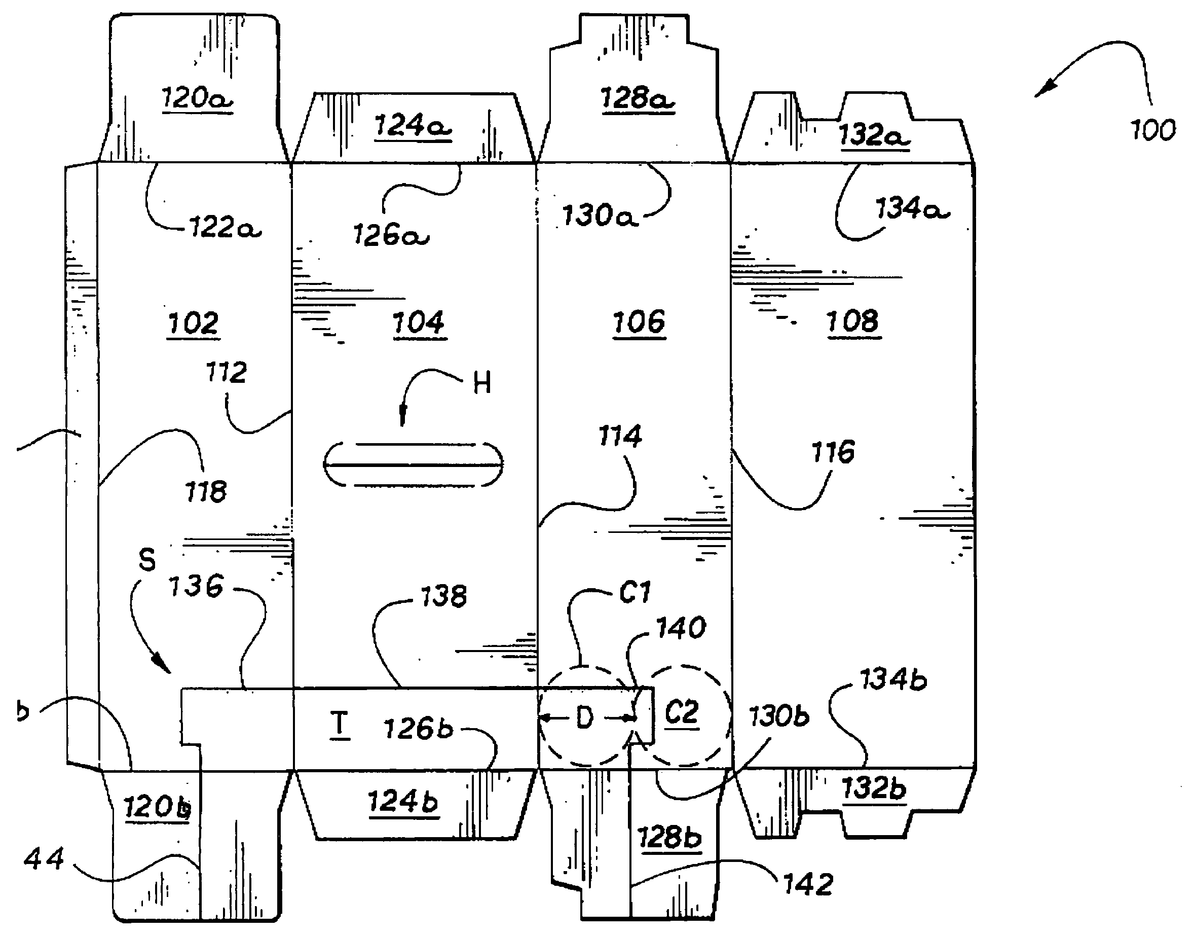
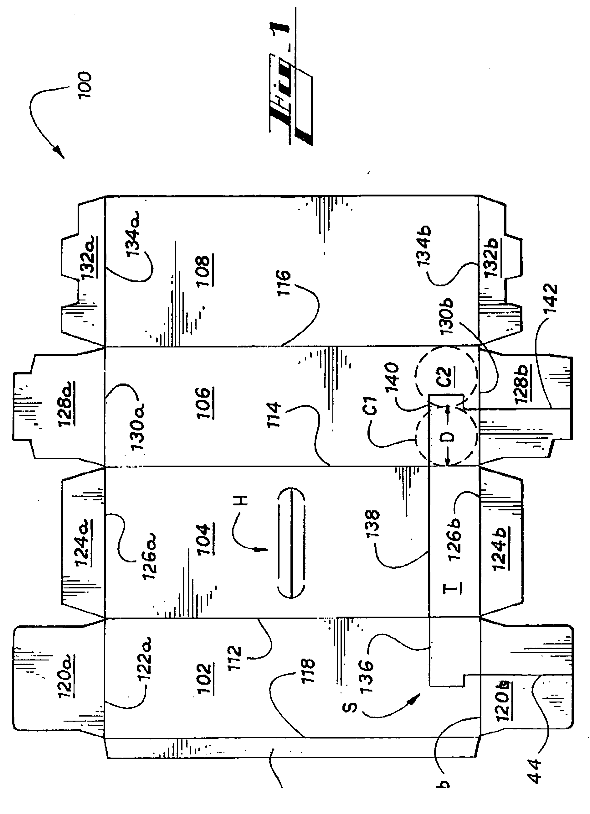
[0036] The trough T is removed from the carton 100 by tearing severance line S. To ease detachment, there may further comprise tear-initiating means, as illustrated in FIGS. 8-11, and as will be described in greater detail below.

third embodiment

[0037]FIG. 8 is a plan view of a blank for forming a carton (shown in FIG. 9) according to the invention, which further illustrates certain teachings thereof. In addition to tear initiation means, this embodiment differs from the embodiment of FIGS. 5-7 in that the stopper wall W3 is concave with respect to the plane of the base wall. However, even the lowest point P, which may include an extended section, of the stopper wall W3 is disposed at a distance from the base wall that greater than the diameter D of the articles. Thus, the stopper wall W3 provides similar advantages as the previous embodiment, including retention and visibility for the articles remaining in the carton after the detachable portion T3 has been removed.

[0038]FIG. 10 is a plan view of a blank for forming a carton (shown in FIG. 11) according to a fourth embodiment of the invention, which further illustrates certain teachings thereof. In addition to tear initiation means, this embodiment differs from the embodim...


PUM


Abstract

A package includes an article group of at least one row of cylindrical articles enclosed by a carton. The carton includes a plurality of walls and an article dispenser opening formed at the region of intersection of planes of the top wall, the opposed side walls and the end wall. A portion of the article dispenser opening is defined by an end wall severance line having all points disposed at elevations at a distance as measured from the plane of the top wall no greater than the diameter of the substantially cylindrical articles that lie in an upper row of the group. Another portion of the article dispenser opening is defined by side wall severance lines a portion of which is at a distance less than the diameter away from the base wall. No portion of either side wall severance line is oblique with respect to the top wall.

Description

CROSS REFERENCE TO RELATED APPLICATIONS [0001] This is a continuation-in-part of U.S. patent application Ser. No. 11 / 098,937, filed Apr. 4, 2005, which is a divisional of U.S. patent application Ser. No. 10 / 397,646, filed Mar. 26, 2003, now U.S. Pat. No. 6,902,104, issued Jun. 7, 2005, both of which are hereby incorporated by reference.FIELD OF THE INVENTION [0002] The invention relates to cartons, and more particularly, to a carton for multiple articles having a dispenser for constrained removal of individual articles. In particular the invention relates to a carton having a dispenser for retaining and removing articles in the carton. BACKGROUND OF THE INVENTION [0003] Cartons for encasing multiple articles are useful for enabling consumers to obtain and transport a desired quantity of individual articles such as soft drinks or other beverages. When such a multiple-pack of articles is obtained, a consumer frequently desires to remove one article from the carton at a time. Thus, it ...

Claims


Application Information

Patent Timeline
IPC IPC(8): B65D5/00B65D17/00
CPCB65D71/36B65D2571/0058B65D2571/0066B65D2571/00728
Inventor HOLLEY, JOHN M. JR.BATES, AARONAUCLAIR, JEAN-MICHEL
Owner MEADWESTVACO PACKAGING SYST LLC
Features
  • Generate Ideas
  • Intellectual Property
  • Life Sciences
  • Materials
  • Tech Scout
  • Unparalleled Data Quality
  • Higher Quality Content
  • 60% Fewer Hallucinations
Learn More