Microchannnel evaporator assembly

Inactive Publication Date: 2006-06-22
HUSNN
View PDF44 Cites 101 Cited by
  • Summary
  • Abstract
  • Description
  • Claims
  • Application Information

AI Technical Summary

Problems solved by technology

Such a conventional fin-and-tube evaporator coil often displays poor efficiencies in transferring heat from an airflow passing through the coil to the refrigerant passing through the coil.
As a result, the fin-and-tube evaporator coil can be rather large for the amount of heat it can remove from the airflow passing through the coil.
Further, the large

Method used


Image

  • Microchannnel evaporator assembly
  • Microchannnel evaporator assembly
  • Microchannnel evaporator assembly

Examples


Embodiment Construction

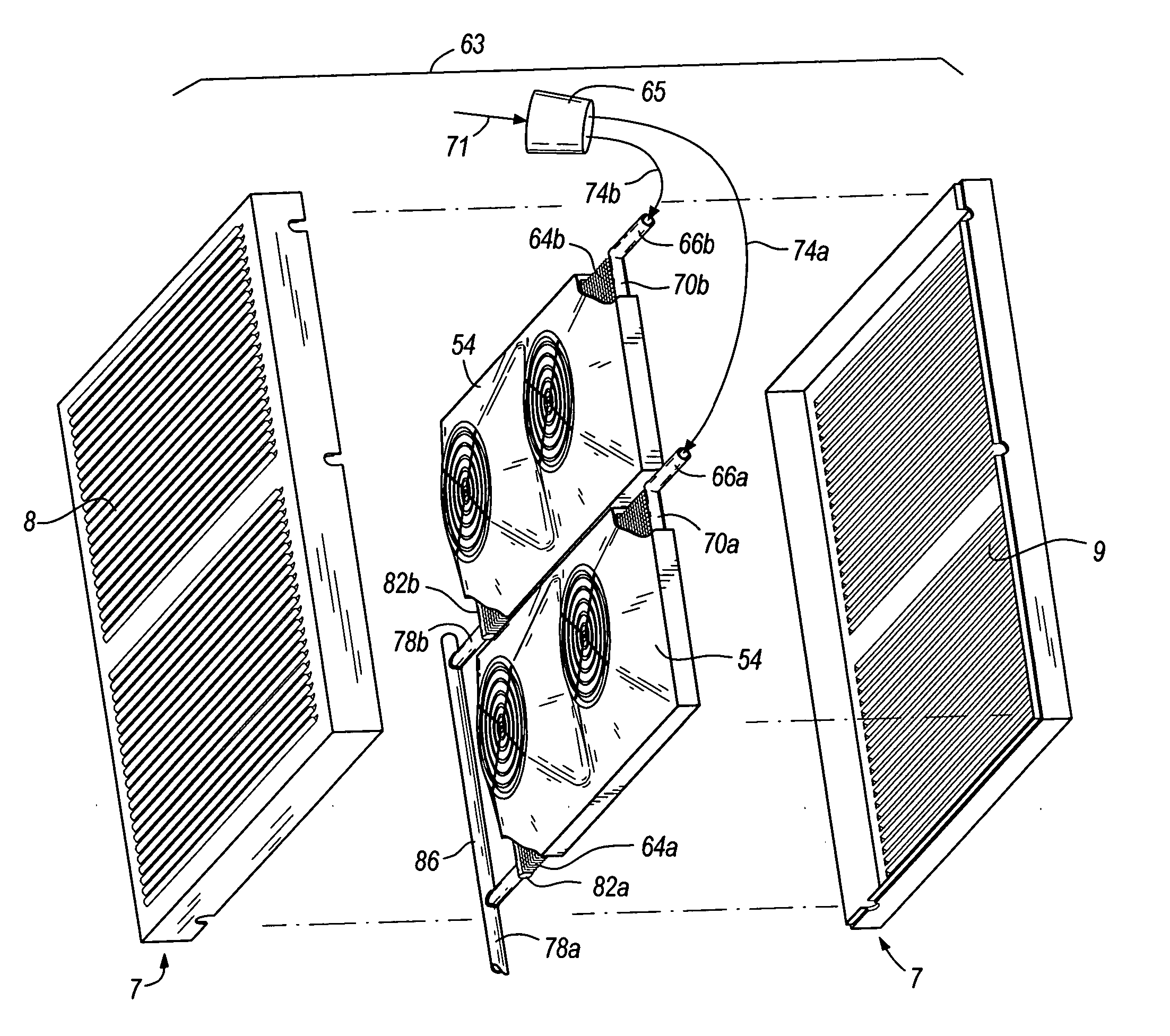
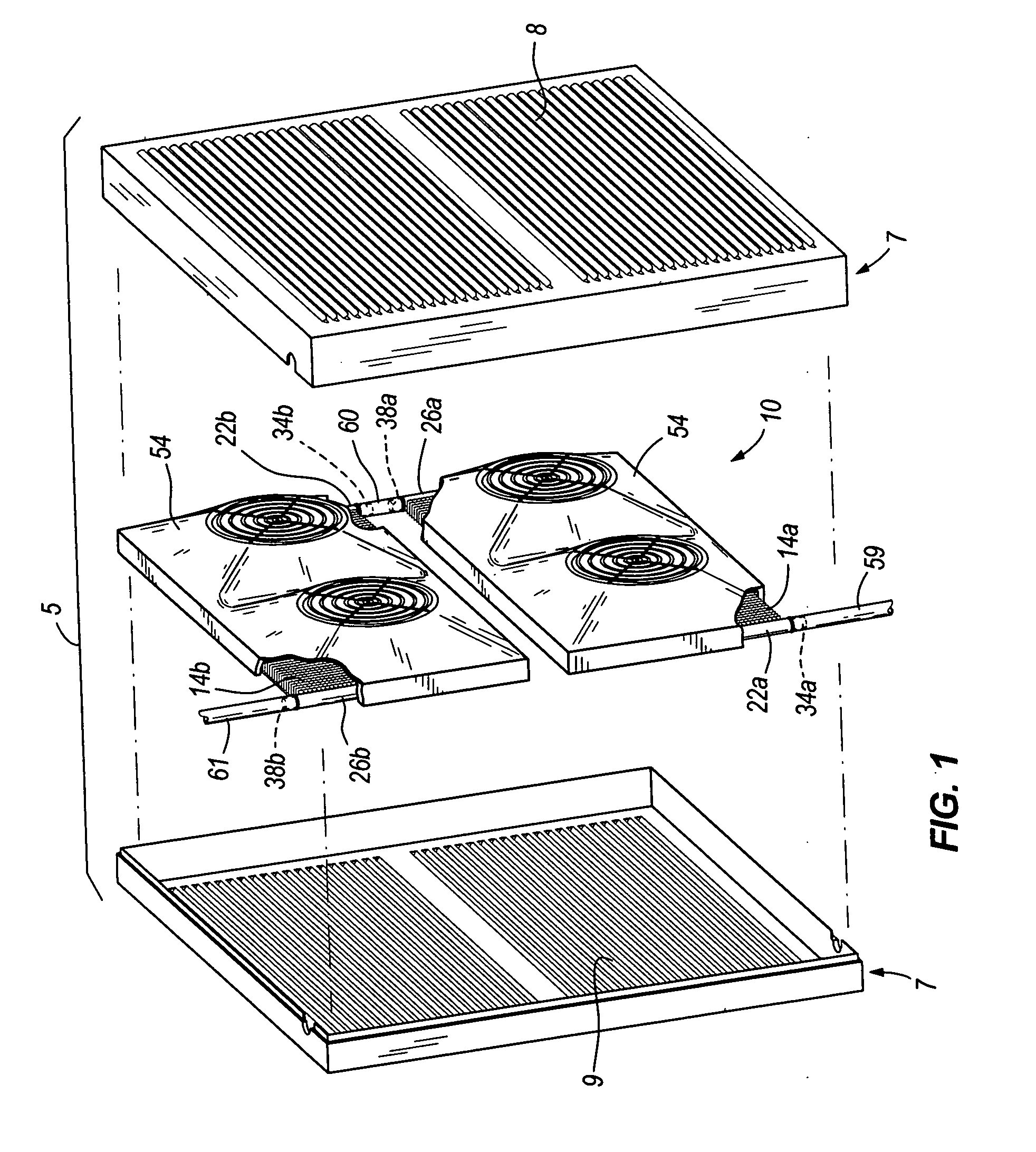
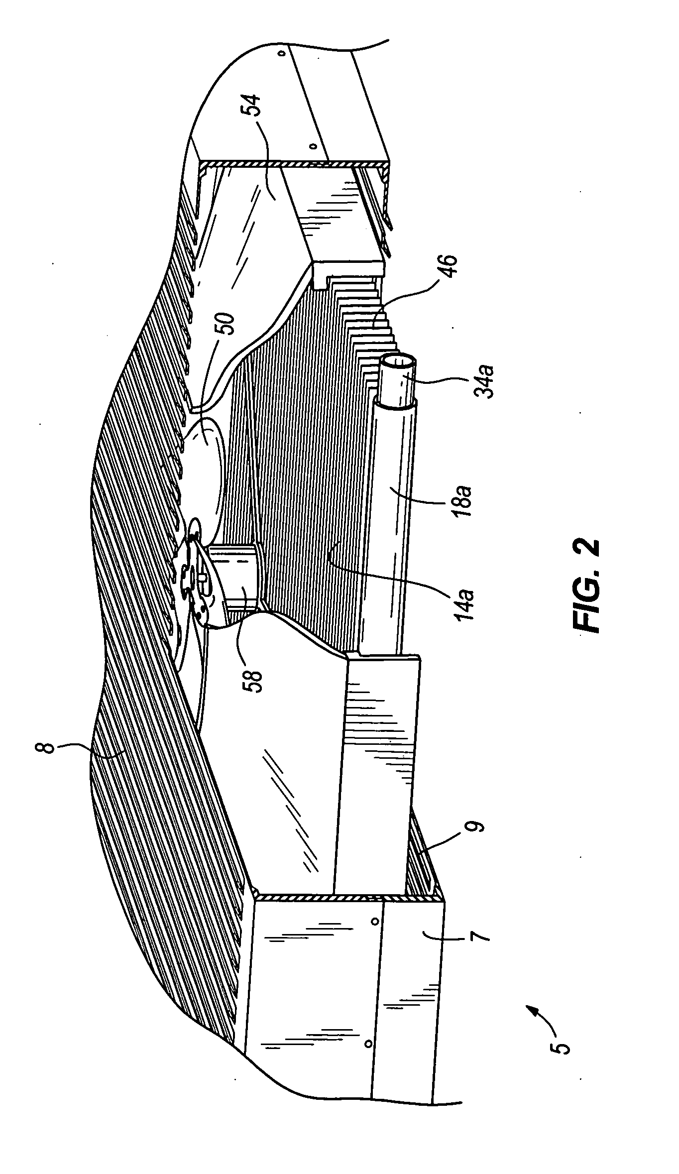
[0028] With reference to FIG. 1, a unit cooler 5 including a first configuration of an evaporator assembly 10 is shown. The unit cooler 5 may be used in a large-scale refrigeration system or a large-scale refrigerated environment, such as a walk-in cooler and a refrigerated warehouse, for example. The evaporator assembly 10 in the unit cooler 5 may therefore recirculate the air in the refrigerated environment to provide a refrigerated airflow to products stored in the walk-in cooler or refrigerated warehouse.

[0029] In a two-phase refrigeration system, the role of the evaporator assembly 10 is to receive low-pressure liquid refrigerant, remove heat from an airflow passing through the evaporator assembly 10, and discharge gaseous refrigerant to one or more compressors (not shown) remotely located from the evaporator assembly 10. The low-pressure liquid refrigerant evaporates as it passes through the evaporator assembly 10, such that the refrigerant passes through a substantial portio...


PUM


Abstract

The present invention provides a unit cooler adapted for use in a refrigerated environment. The unit cooler includes a housing adapted to be positioned within the refrigerated environment and at least one microchannel evaporator coil supported by the housing. The at least one microchannel evaporator coil includes an inlet manifold and an outlet manifold. The inlet manifold has an inlet port for receiving refrigerant, and the outlet manifold has an outlet port for discharging the refrigerant.

Description

FIELD OF THE INVENTION [0001] This invention relates generally to evaporator coils, and more particularly to evaporator coils for use in large-scale refrigeration systems. BACKGROUND OF THE INVENTION [0002] Typical large-scale refrigeration systems, such as those utilized in large-scale refrigerated environments (e.g., walk-in coolers or refrigerated warehouses), often include a single, large conventional fin-and-tube evaporator coil. Such a conventional fin-and-tube evaporator coil often displays poor efficiencies in transferring heat from an airflow passing through the coil to the refrigerant passing through the coil. As a result, the fin-and-tube evaporator coil can be rather large for the amount of heat it can remove from the airflow passing through the coil. Further, the larger the evaporator coil becomes, the more refrigerant used in the refrigeration system, thus effectively increasing potential damage to the environment by an accidental atmospheric release. [0003] Another fo...

Claims


Application Information

Patent Timeline
IPC IPC(8): F25D21/12F28F1/00F25B39/02
CPCF25B39/022F25B2500/01F28D1/05383F28F1/022F28F9/0275F28F9/262F28F2260/02
Inventor MERKYS, JUSTIN P.MCALPINE, DOUGSTREET, NORMAN E.ZERBE, PHIL K.
Owner HUSNN
Why Eureka
Try Eureka