Fuel injector retention clip

a technology of fuel injector and retention clip, which is applied in the direction of low-pressure fuel injection, machines/engines, mechanical equipment, etc., can solve the problems of fuel rails causing distortion and/or movement, fuel performance and/or compliance with applicable vehicle emission requirements, undetectable stress,

Active Publication Date: 2006-06-29
MILLENNIUM INDS
View PDF19 Cites 59 Cited by
  • Summary
  • Abstract
  • Description
  • Claims
  • Application Information

AI Technical Summary

Benefits of technology

[0015] Other features of the invention will become more app

Problems solved by technology

Improperly targeted fuel injectors may derogate engine performance and/or compliance with applicable vehicle emission requirements.
Once the fuel injector nozzles have seated in-properly targeted positions in the socket receptacles, a need for further tightening of such fasteners in order to secure the fuel rail to the engine may induce undesired stress, distortion and/or movement.
For example, if fuel injector nozzles have been seated in properly targeted positions in respective socket receptacles in engine air intake manifold runners before the fuel rail attachment fasteners have been fully torqued, the fuel rail may disto

Method used


Image

  • Fuel injector retention clip
  • Fuel injector retention clip
  • Fuel injector retention clip

Examples


Embodiment Construction

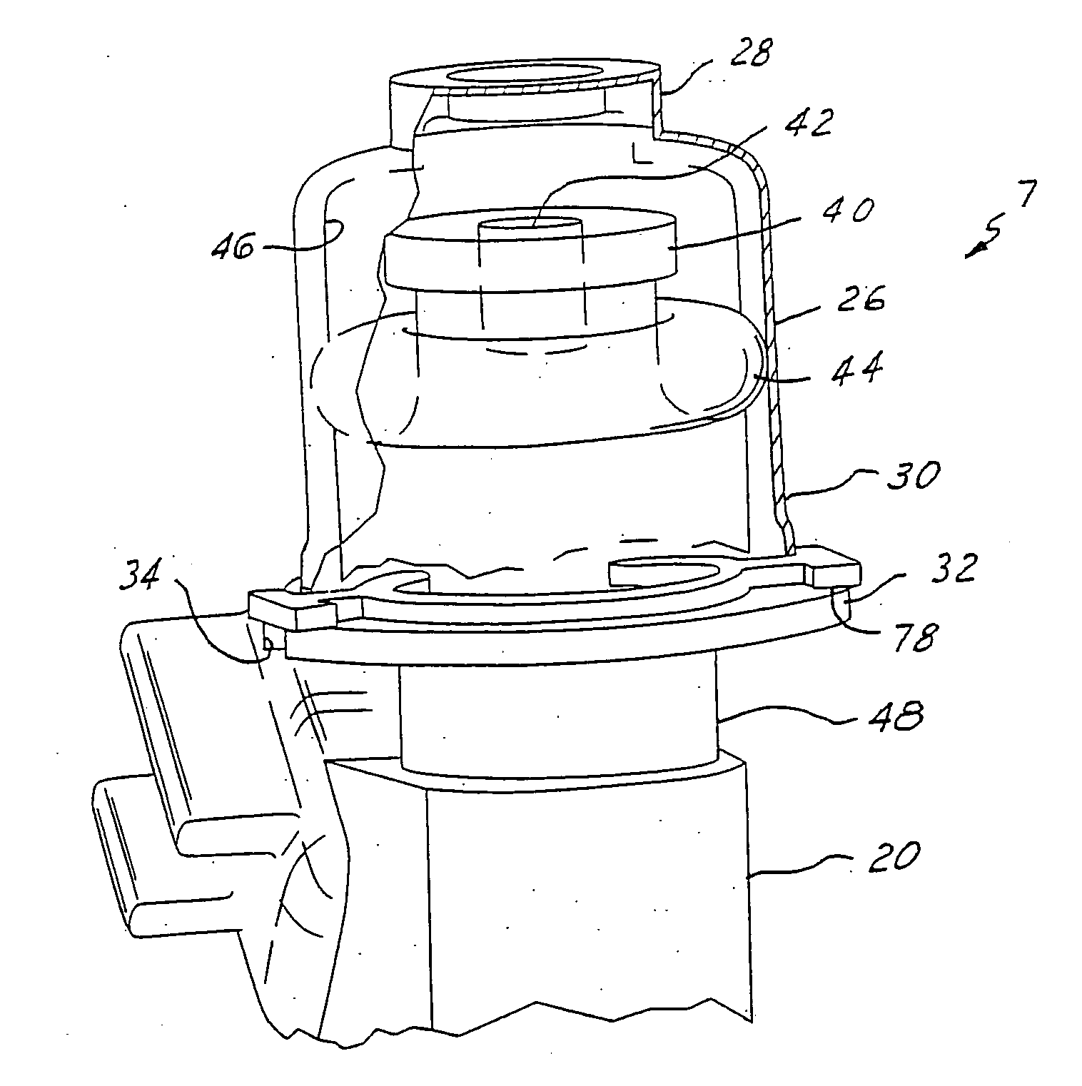
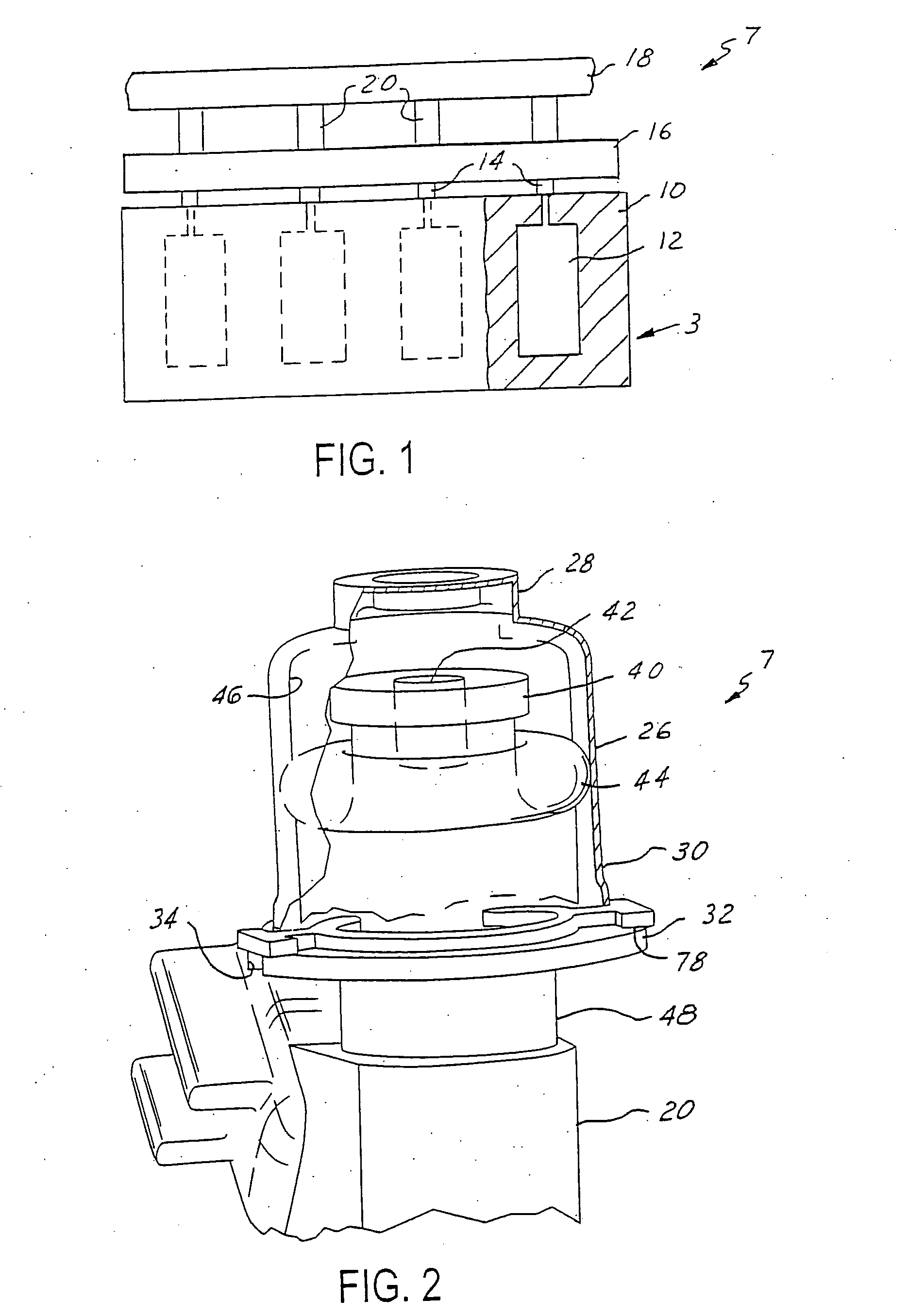
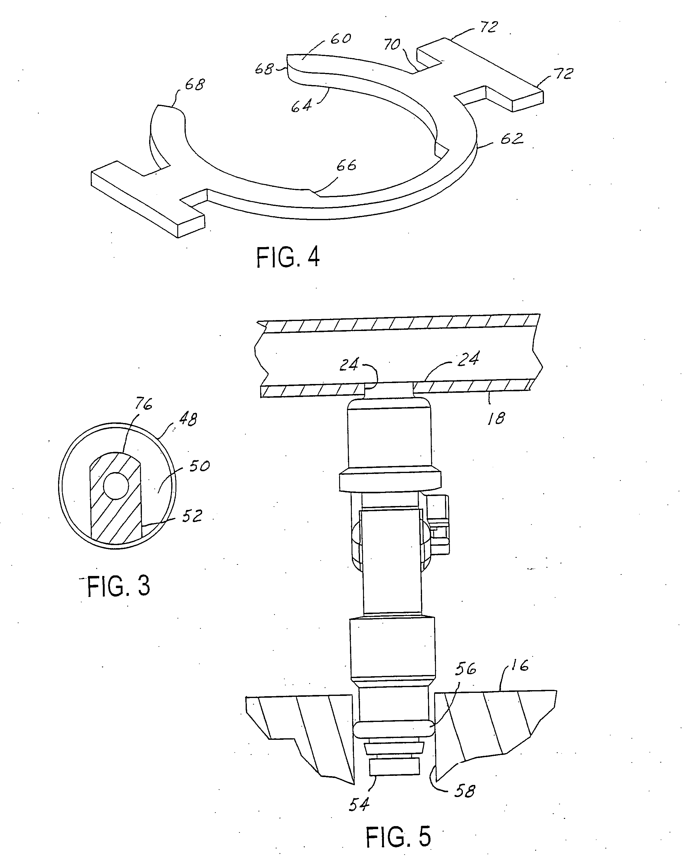
[0046]FIG. 1 illustrates a spark-ignited, internal combustion vehicle engine 3 having an arrangement of a fuel delivery system 7 according to the present invention. The vehicle engine 3 as schematically shown has an engine block 10. The engine block 10 has a bank of combustion chambers 12. The combustion chambers 12 are fluidly connected with runners 14 of an air intake manifold 16. Connected between the air intake manifold 16 and a pressurized fuel rail 18 are a series of fuel injectors 20. The fuel injectors 20 meter fuel from the fuel rail 18 to the runners 14. In another embodiment of the present invention (not shown), the fuel injectors 20 are inserted with a passage connecting them directly with the combustion chambers 12. Typically the fuel rail 18 will be connected to the intake manifold 16 by a series of brackets (not shown). The fuel injectors 20 are typically top feed electric operated type fuel injectors. The fuel injectors may be single or multiple orifice type fuel inj...


PUM


Abstract

A fuel delivery system in accordance with the present invention comprises a fuel rail having an outlet opening and an outlet cup that is insertable into the outlet opening. The cup includes a flange. The flange includes at least one tab extending therefrom. The cup further defines a vertical axis extending therethrough. The system further includes a fuel injector with an inlet insertable within the cup. The system still further includes a retention clip. The clip includes an inner peripheral surface, at least a portion of which is configured for engagement with the injector when the clip and injector are assembled together. The clip further includes at least one arm, the arm further including a finger configured for spring engagement with the tab of the cup. The clip is operative to limit the movement of the fuel injector when it is assembled with the clip and inserted in the cup.

Description

CROSS REFERENCE TO RELATED APPLICATIONS [0001] This application is a Continuation-in-Part of U.S. patent application Ser. No. 11 / 003,059 filed Dec. 3, 2004 and currently pending, which is hereby incorporated by reference in its entirety.BACKGROUND OF THE INVENTION [0002] 1. Field of the Invention [0003] The invention relates to a fuel delivery system arrangement for connecting an electric operated fuel injector between a fuel rail and an air intake of a spark-ignited, internal combustion engine. [0004] 2. Discussion of Related Art [0005] Spark-ignited, fuel-injected internal combustion engines are often used in automotive vehicles. Fuel is injected into an intake system of such an engine by electric operated fuel injectors of a fuel rail (sometimes referred to as a fuel manifold) assembled to the engine. [0006] Targeted types of fuel injectors inject fuel into the vehicle engine in a direction, or directions, that are other than along the fuel injector axial centerline. A split stre...

Claims


Application Information

Patent Timeline
IPC IPC(8): F02M61/14
CPCF02M55/005F02M61/14F02M61/145F02M61/168F02M69/042Y10T24/44F02M2200/8053F02M2200/856F02M2200/852F02M2200/853F02M69/465
Inventor ZDROIK, MICHAEL J.DOHERTY, ROBERT
Owner MILLENNIUM INDS
Why Eureka
Try Eureka