Storage controller and method for storage control

a storage controller and controller technology, applied in the field of storage controllers, can solve problems such as unsatisfactory sequential read performance, and achieve the effect of improving sequential read performance and data redundancy

Active Publication Date: 2006-06-29
FUJITSU LTD
View PDF4 Cites 53 Cited by
  • Summary
  • Abstract
  • Description
  • Claims
  • Application Information

AI Technical Summary

Benefits of technology

[0015] The objective of the present invention is to perform mapping for improving the sequential read perfor

Problems solved by technology

This is not desirable from the viewp

Method used


Image

  • Storage controller and method for storage control
  • Storage controller and method for storage control
  • Storage controller and method for storage control

Examples


Embodiment Construction

[0035] The preferred embodiments for implementing the present invention are described in detail below, in reference to the diagrams.

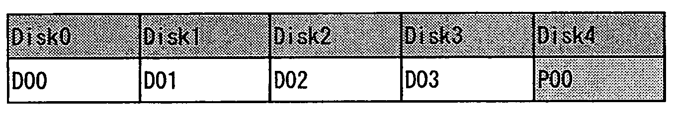
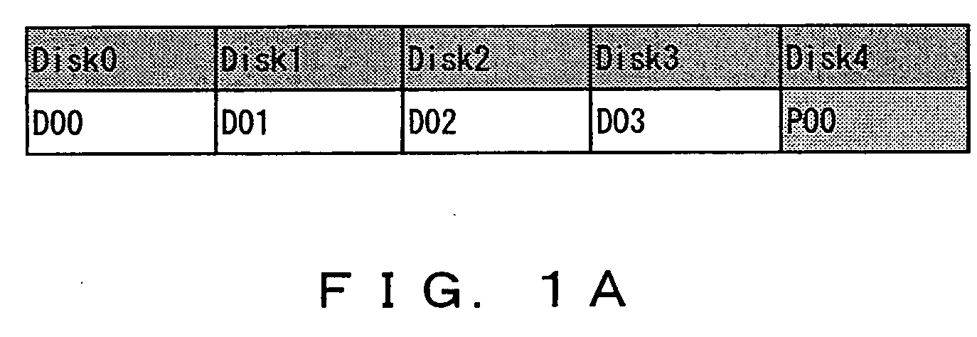
[0036]FIG. 2A is a principle diagram of a storage controller according to the present invention. The storage controller 101 in FIG. 2A comprises a determination device 111 and a controller 112 and realizes data redundancy by controlling the distribution and storage of a stripe, comprising N number of data strips and M number of parity strips of a different type, to N+M number of memory devices, 102-1, 102-2, - - - 102-(N+M).

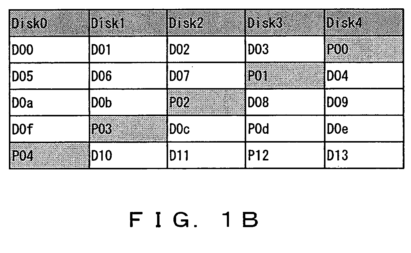
[0037] The determination device 111 determines the storage destination memory devices for the N number of data strips and the M number of parity strips of different types, so as to avoid continuously storing the parity strips to the same memory device between two continuous stripes when the memory devices, 102-1, 102-2, - - - 102-(N+M), store a plurality of stripes. The controller 112 controls the storage of the N number of data st...


PUM


Abstract

Storage destination controller devices wherein N number of data strips and M number of parity strips comprised in each stripe are determined so that the parity strips are not continuously stored to the same memory device between two consecutive stripes when a plurality of stripes, each comprising the N number of data strips and the M number of parity strips of different types, are distributed and stored to the N+M number of memory devices.

Description

BACKGROUND OF THE INVENTION [0001] 1. Field of the Invention [0002] The present invention relates to a storage controller which controls the distribution and storage of data and parities in a plurality of memory devices such as RAID (Redundant Array of Inexpensive Disks), and a method thereof. [0003] 2. Description of the Related Art [0004] RAID is a technology wherein a plurality of hard disks are combined and controlled as one redundant hard disk and is classified into seven levels, from RAID 0 to RAID 6, according to the methods for data allocation to disks and data redundancy. Out of these levels, in RAID 3 to Raid 6, redundancy is realized by storing parities, which have been created from data, independently of the data (for example, refer to Japanese Patent Laid-Open Publication No. 2000-259359). [0005] The mapping of RAID 5 is described first. In RAID 5, performance enhancement is achieved by changing the disk which handles parities, fixed in RAID 4, every time stripes change...

Claims


Application Information

Patent Timeline
IPC IPC(8): G06F11/00
CPCG06F3/0613G06F3/065G06F3/0689G06F11/1076G06F2211/1057G11B2220/415H04N21/21H04N21/23G06F3/06G06F3/00
Inventor MOCHIZUKI, SHINYAITO, MIKIODAIKOKUYA, HIDEJIROIKEUCHI, KAZUHIKOTAKAHASHI, HIDEOKONTA, YOSHIHITOSATO, YASUTAKEOCHI, HIROAKIMAKINO, TSUKASAKUBOTA, NORIHIDE
Owner FUJITSU LTD
Why Eureka
Try Eureka