Apparatus and method for placement of a water closet fitting

Inactive Publication Date: 2006-07-06
3M INNOVATIVE PROPERTIES CO
View PDF84 Cites 4 Cited by
  • Summary
  • Abstract
  • Description
  • Claims
  • Application Information

AI Technical Summary

Problems solved by technology

Current methods for placing water closet flanges in fluid communication with waste pipes are labor intensive and/or prone to error.
Such installations and testing often occurs before any partition walls, or other notable landmarks, have been constructed inside the structure, whi

Method used


Image

  • Apparatus and method for placement of a water closet fitting
  • Apparatus and method for placement of a water closet fitting
  • Apparatus and method for placement of a water closet fitting

Examples


Embodiment Construction

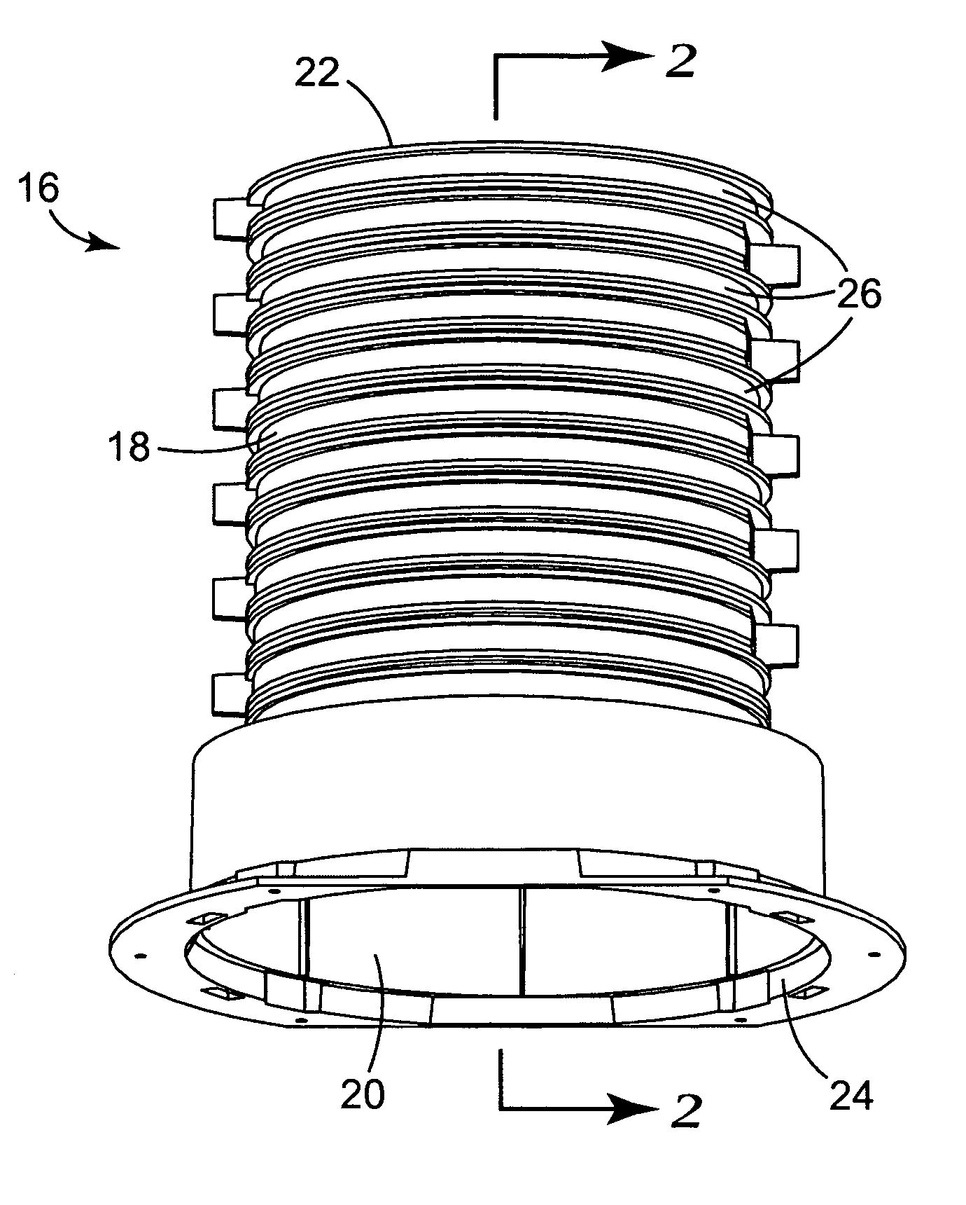
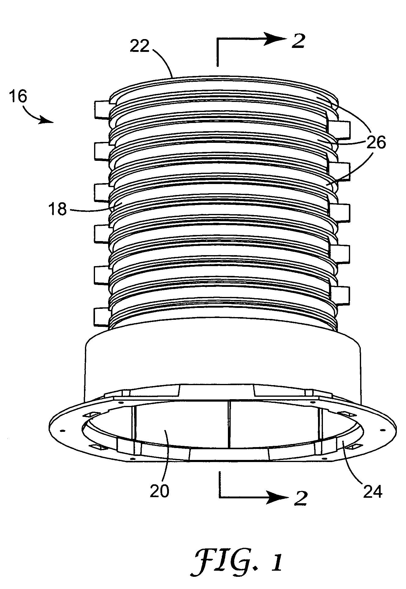
[0022] The present invention includes a water closet fitting for mounting to a channel extending through a concrete floor upon which a water closet is to be installed. The channel accommodates fluid connection means for connecting the water closet to a waste pipe of a plumbing system. FIGS. 1-2 show an example of a caste-in-place channel body 16 configured to form such a channel, with FIG. 1 showing a perspective view of channel body 16 and FIG. 2 showing a sectional view of channel body 16 taken along line 2-2 of FIG. 1.

[0023] Channel body 16 includes annular sidewall 18 that defines passage 20 having inlet 22 and outlet 24. As shown in FIGS. 1 and 2, sidewall 18 of channel body 16 includes a series of bands 26 which may be selectively removed to alter the length of passage 20. This variable length feature allows channel body 16 to be installed in floors of different thickness. Further description of channel bodies similar to channel body 16 is included in U.S. Pub. No. 2004 / 00161...


PUM


Abstract

A water closet fitting allows placement of a water closet flange in fluid communication with a waste pipe of a plumbing system. The water closet fitting includes a cap with a removable, pressure resistant cap portion sealing off an inlet. The cap portion may be removed to permit fluid to flow through the inlet. The water closet flange is sealably mounted to the water closet fitting once the cap portion is removed. The waste pipe is sealably connected to the water closet fitting below the cap.

Description

BACKGROUND OF THE INVENTION [0001] The present invention relates generally to accommodations for plumbing fittings. More specifically, the present invention relates to water closet fittings for use in connecting water closets to plumbing systems. [0002] A common method for installing water closets involves forming a channel through a concrete floor upon which a water closet is to be installed. The channel accommodates fluid connection means for connecting the water closet to a waste pipe of a plumbing system. Various methods are used for forming such channels through concrete floors. In one method, concrete is poured around either a cast-in-place channel device or a sleeve. In another method, the channel is formed after pouring the concrete floor by core drilling through the concrete floor to form the channel. [0003] After a channel has been provided through the concrete floor, a water closet flange is installed near an inlet end of the channel. The water closet flange is typically ...

Claims


Application Information

Patent Timeline
IPC IPC(8): E03D11/00E03D11/14
CPCE03D11/16
Inventor REIER, MATTHEW D.DECKER, DANA A.
Owner 3M INNOVATIVE PROPERTIES CO
Why Eureka
Try Eureka