Automatic actuator to flush toilet

a technology of automatic actuator and toilet, which is applied in the direction of flushing devices, water installations, constructions, etc., can solve the problems of difficult access to the toilet flush handle, difficult conversion of a conventional toilet to one capable of automatic flushing after use, and high cost, and achieves the effect of easy replacement and easy installation

Active Publication Date: 2008-03-27
ZURN INDS
View PDF56 Cites 36 Cited by
  • Summary
  • Abstract
  • Description
  • Claims
  • Application Information

AI Technical Summary

Benefits of technology

[0017] It is therefore an object of the invention to provide an automatic toilet flushing system for a conventional toilet having a reservoir tank and a toilet bowl, wherein the actuator is easily installed inside the reservoir tan

Problems solved by technology

Also, people suffering from temporary or permanent disabilities may find it difficult to access a toilet flush handle, which is usually located rearwardly of the toilet seat.
In the prior art automatic toile

Method used


Image

  • Automatic actuator to flush toilet
  • Automatic actuator to flush toilet
  • Automatic actuator to flush toilet

Examples


first embodiment

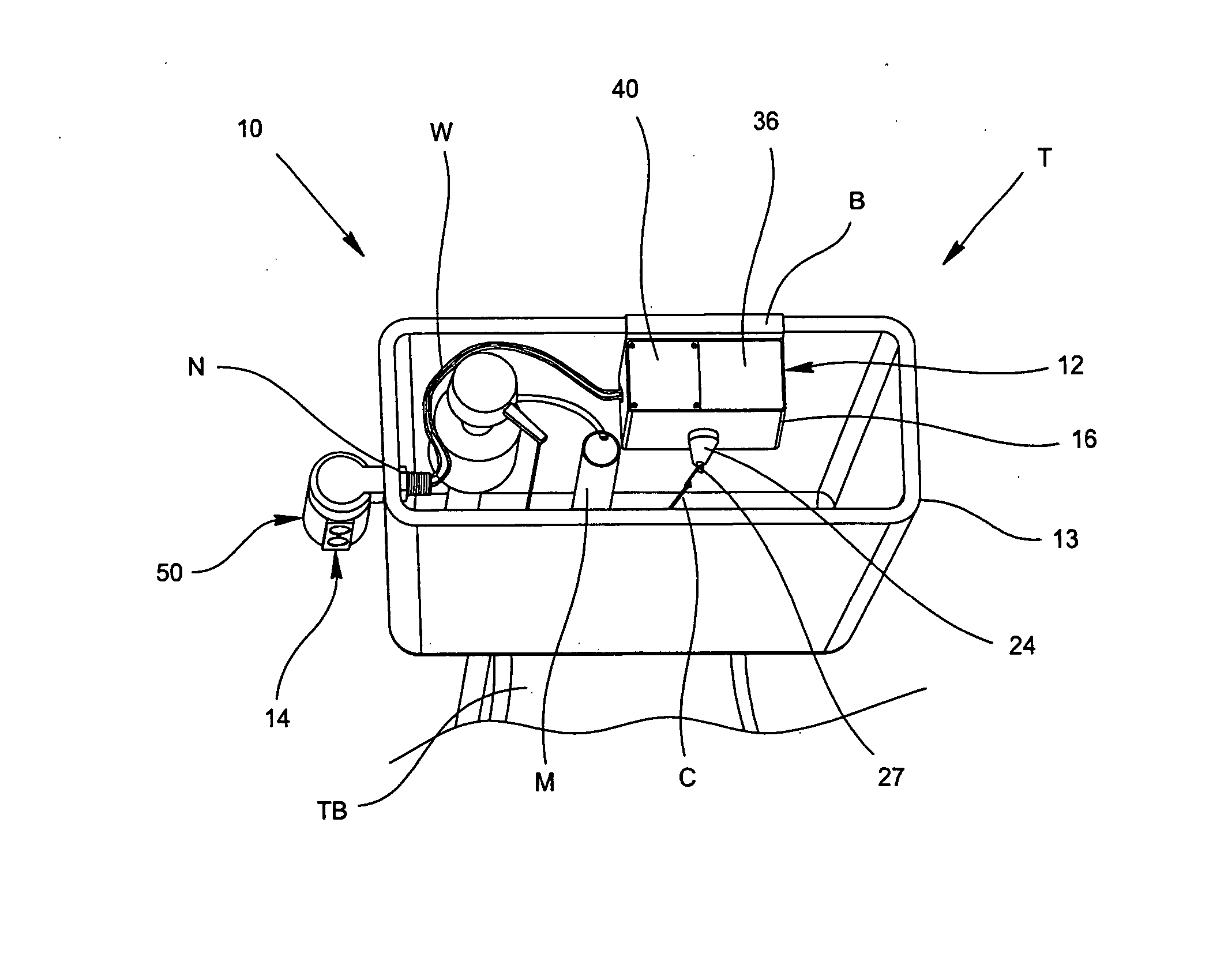
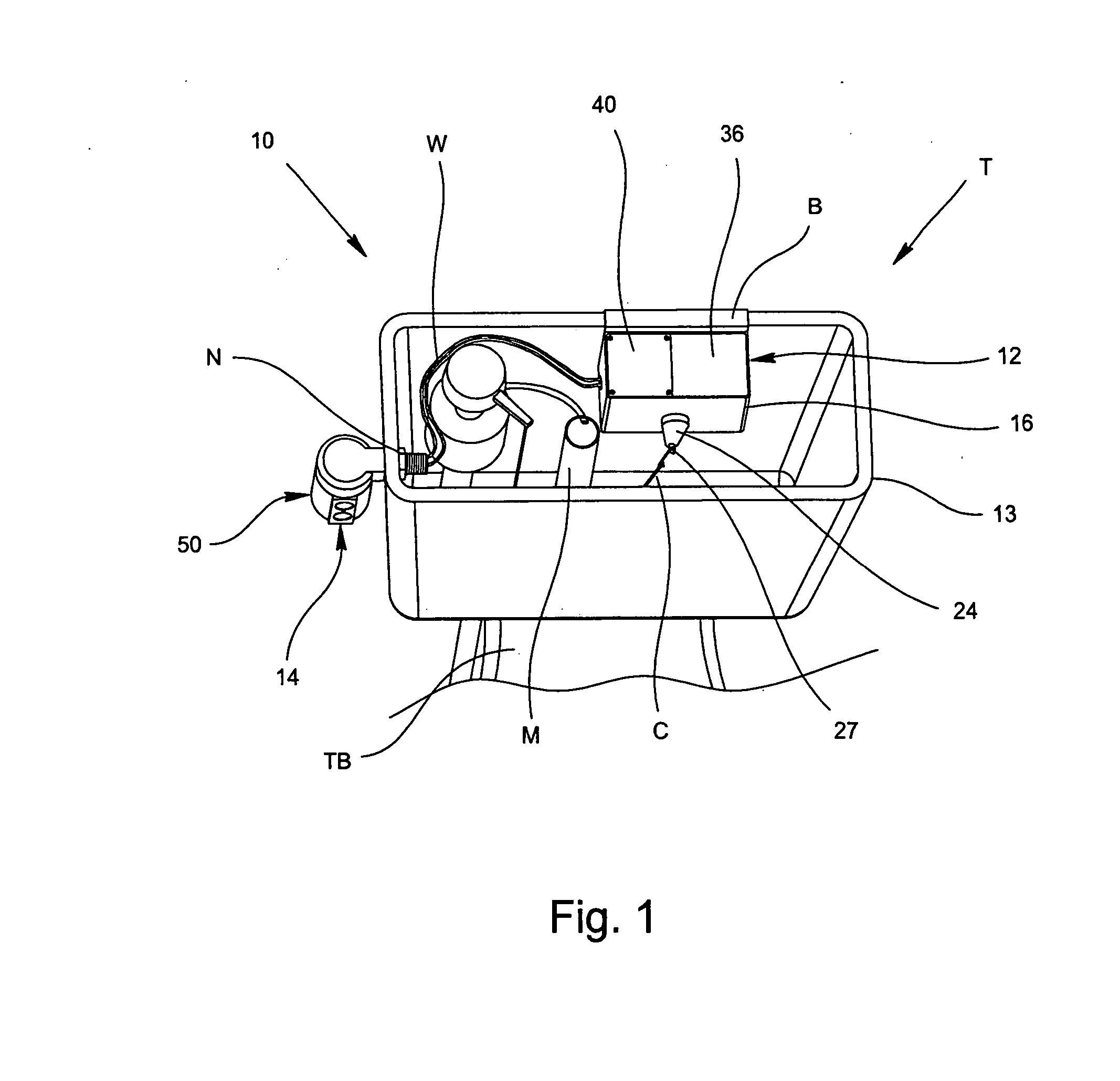
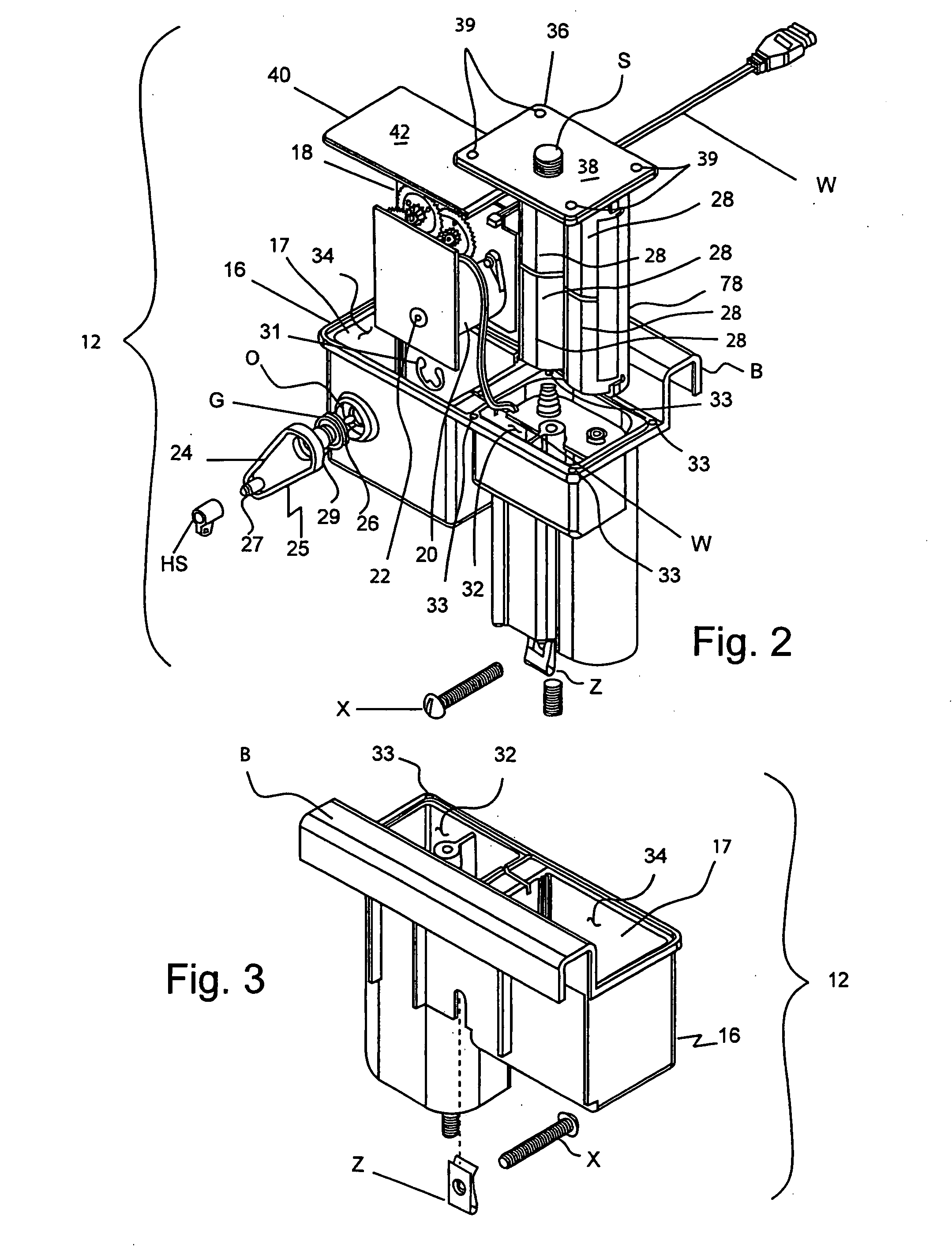
[0032] Referring to FIG. 1, the invention provides an automatic toilet flushing system 10 for a conventional toilet T which has a toilet bowl TB and a reservoir tank 13. The automatic toilet flushing system 10 includes an actuator 12 mounted in the reservoir tank 13 and in communication with a sensor 14, which is mounted into a sidewall of the conventional toilet T. The sensor 14 may be in communication with the actuator 12 via a wire W or via a transmitted signal (i.e., wireless communication). In the wireless communication arrangement, a radio frequency transmitter can be provided in the sensor 14 and a corresponding radio frequency receiver may be provided in the actuator 12. Referring to FIG. 2, the actuator 12 is housed in an actuator box 16 and includes a gear train 18, a motor 20 having an output shaft 22, and an external rotating arm 24 having a shaft 26. The output shaft 22 of the motor 20 is rotatably connected to the gear train 18, and the external arm 24 is rotatably con...

second embodiment

[0039]FIG. 5 shows the sensor 14 of the automatic flushing system 10 used to detect when a human body comes within a predetermined distance with respect to a toilet bowl (not shown). The sensor 14 is preferably located in the manual flush handle hole of a conventional toilet, thus replacing the manual flush handle as shown in FIG. 1. However, the sensor 14 can be located anywhere in the bathroom as long as it can detect a person at the toilet, more about which will be discussed relative to the invention of FIG. 8. The sensor 14 preferably uses ultrasound technology to detect a user near the toilet. By using ultrasound technology, false detection due to moisture, such as steam, is eliminated. Also, ultrasound technology is not sensitive to color and can operate in all shades of light. The sensor 14 can also utilize magnetic, electrostatic, optical and electromagnetic principles for detection of a person in the vicinity of the sensor 14. Other types of sensors may be used, such as hea...


PUM


Abstract

An automatic toilet flushing system, for use with conventional toilets, includes a sensor, an actuator and a flushing mechanism. The actuator has a gear train, a motor, a pivotal arm connected to the gear train, and a power source connected to the motor for rotating the shaft of the motor which rotates the gear train for pivotal movement of the arm. The flushing mechanism includes a flapper valve and the pivotal arm is connected to the flapper valve via a bead chain and a handle swivel or a tab mounted on the pivotal arm. The sensor may replace the flush handle or the flush handle and the sensor may both be provided. A kit and a method for converting a manual flushing system to the automatic toilet flushing system are also provided.

Description

CROSS REFERENCE TO RELATED APPLICATION [0001] This application is based on Provisional Patent Application No. 60 / 793,916 filed Apr. 21, 2006, on which priority of this patent application is based, and which is hereby incorporated by reference in its entirety.BACKGROUND OF THE INVENTION [0002] 1. Field of the Invention [0003] The present invention relates generally to automatic toilet flushing systems and, more particularly, to an automatic actuator for flushing toilets, such as home toilets or other toilets found in private dwellings or facilities. [0004] 2. Description of Related Art [0005] There are many commercially available automatic toilet flushing systems for use in various commercial and industrial establishments. Also, automatic toilet flushing systems for use in conventional home toilets or other toilets found in private dwellings have been disclosed, for example, in U.S. Pat. No. 4,141,091 to Pulvari; U.S. Pat. No. 5,003,643 to Chung; and U.S. Pat. No. 6,202,227 to Gurowi...

Claims


Application Information

Patent Timeline
IPC IPC(8): E03D5/10
CPCE03D5/105
Inventor FUNARI, MICHAEL A.PHILLIPS, JEFFREY T.VANHOY, BRIANLEVINER, ROY F. III
Owner ZURN INDS
Why Eureka
Try Eureka