Waterless vacuum toilet system for aircraft

a vacuum toilet and aircraft technology, applied in the field of vacuum toilet systems, can solve the problems of not being well suited to commercial passenger transport vehicles, not having waste contact surfaces, and only limited capacity of transporting vehicles, so as to increase the seating capacity of aircraft, reduce weight, and save weight

Inactive Publication Date: 2005-12-20
AIRBUS OPERATIONS GMBH
View PDF21 Cites 33 Cited by
  • Summary
  • Abstract
  • Description
  • Claims
  • Application Information

AI Technical Summary

Benefits of technology

[0013]The above objects have been achieved in a toilet system according to the invention in which the toilet bowl is connected by a suction valve to a waste collection tank, and in which at least some of the system components that come into contact with waste material are provided with a nanocoating. Particularly at least a portion of the inner bowl surface of the toilet bowl itself is provided with a thin film coating deposited by nanotechnology processes. Preferably, the nanocoating is provided at least on the entirety of the waste-contacting inner surface area of the toilet bowl, whereby the nanocoating may have a large surface area, such as at least 250 cm2 or even at least 500 cm2. Such a nanocoating significantly reduces or eliminates the adhesion of fecal residue and other wastes on the waste-contacting surfaces of the toilet bowl, the waste line, the flush valve, and / or the waste tank, and therefore eliminates the need for flushing the toilet bowl with a flushing liquid. The nanocoating also avoids the need to provide wrappers or the like for encapsulating the fecal waste in the toilet bowl, as in some prior art systems. These features in turn simplify and reduce the weight of the overall toilet system.
[0014]According to a further feature of the toilet system according to the invention, the flush water and consequently the flush water circuit are completely eliminated by instead providing an “air flushing” arrangement. This simplifies the system by reducing the number of its components, and reduces the maintenance and repair effort. By applying suction through the toilet bowl outlet during the toilet bowl emptying process, an airflow is sucked into the bowl and downwardly to the bowl outlet, which assists in sweeping and removing the fecal und urine waste from the (preferably nano-coated) waste-contacting surfaces of the bowl downwardly to the bowl outlet. The airflow can be enhanced or especially directed along the waste-contacting surfaces by airflow directing means such as an air jet arrangement (passive or active), for example including an annular air gap forming an annular nozzle that communicates the airflow from an air plenum space in a toilet-surrounding shroud into the interior of the toilet bowl and particularly directs the airflow toward and along the inner waste-contacting surfaces of the toilet bowl. By means of this airflow, it is possible to achieve good cleansing of the (preferably nano-coated) waste-contacting surfaces of the toilet bowl, without flush water. A very small amount of a deodorizer and / or disinfectant may be separately applied to the interior of the toilet bowl.
[0015]The invention further provides a method for manufacturing a toilet system according to the invention. The surface of the toilet bowl to be coated with the nanocoating can be pretreated with grinding, polishing and surface cleaning operations. The nanocoating can be applied by means of cathodic sputtering or gas phase deposition processes such as chemical vapor deposition or physical vapor deposition processes. Waste contamination and adhesion of particles can be avoided particularly by applying the nanocoating to the waste-contacting surface portion of the toilet bowl that comes into contact with waste materials or is exposed to a passenger.
[0017]The toilet system according to the invention is particularly advantageous because it provides a substantial reduction in weight relative to the conventional systems. This is especially important for the use of such toilet systems in aircraft. The weight that is saved due to the elimination of flush water can be used, for example, to allow increasing the seating capacity in the aircraft.

Problems solved by technology

Transportation vehicles, particularly aircraft, have only a limited capacity for carrying flushing liquid for rinsing or flushing toilets and for storing the waste water that results.
In other words, such systems do not have any waste-contacting surfaces in the toilet bowl or waste lines, because the waste is fully encapsulated in a wrapper.
Such systems are not well suited to applications in commercial passenger transport vehicles such as aircraft, because they are not sufficiently robust and reliable.
Such items will inevitably puncture the waste-encapsulating wrapper, causing feces to directly contact, soil and adhere to the inner surfaces of the toilet bowl and waste line.
Also in such systems, the wrapper-providing arrangement is highly subject to malfunction and failure, and / or requires proper operating efforts and procedures by the toilet user.
This is particularly true for large capacity aircraft that fly long distances (i.e. long flight durations) and, accordingly, must otherwise carry an enormous amount of water.

Method used


Image

  • Waterless vacuum toilet system for aircraft
  • Waterless vacuum toilet system for aircraft
  • Waterless vacuum toilet system for aircraft

Examples


Embodiment Construction

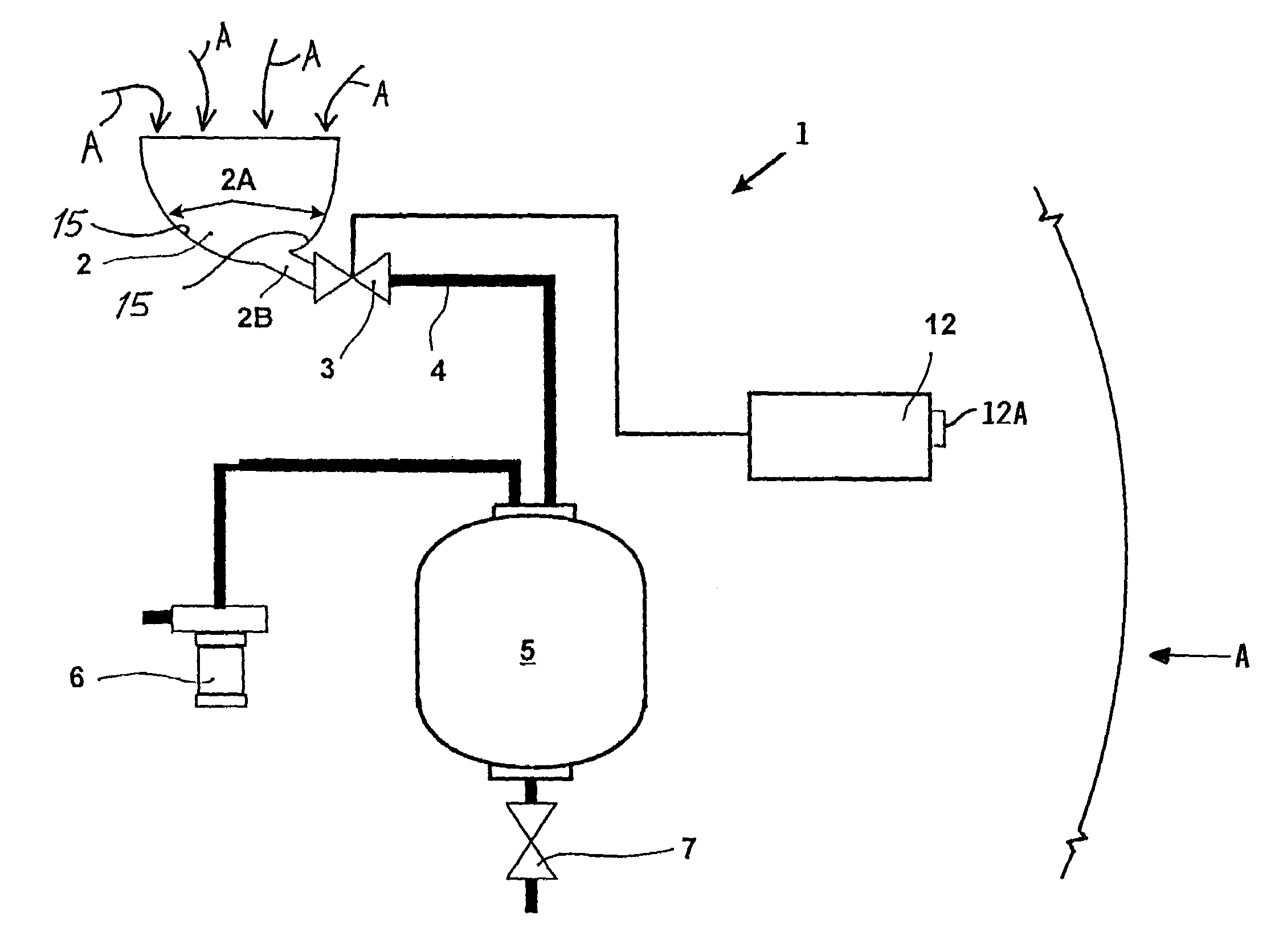
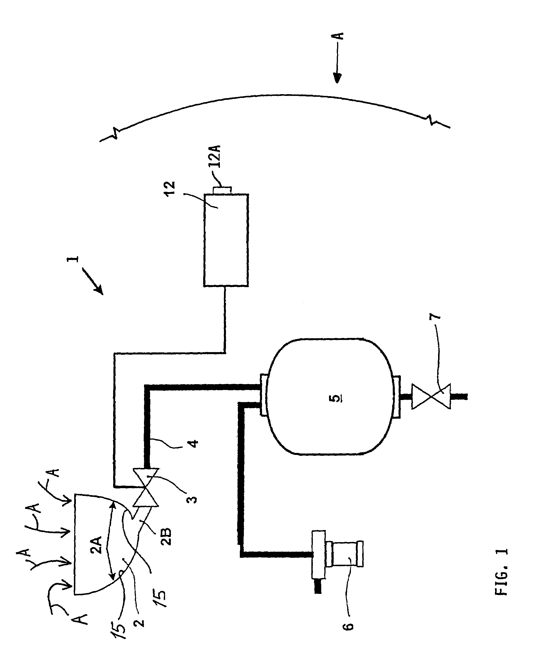
[0027]FIG. 1 is a schematic representation of a toilet system 1 according to the invention in an aircraft AC schematically represented by a broken section of a wall of the aircraft fuselage thereof. The toilet system 1 comprises essentially at least one toilet bowl 2 that is connected via a waste valve 3 to a waste collection pipe 4. The term toilet bowl herein includes all possible types and configurations of toilets for the disposal of urine and / or fecal waste including sit-down toilets, crouching-type toilets, urinals, etc., while the drawings schematically show a sit-down toilet configuration as an example. It is possible to connect a plurality of toilets 2 located at various locations in the aircraft AC to the waste collection pipe 4. The waste collection pipe 4 includes pipes, conduits, hoses, or lines that are used to convey waste material. The waste collection pipe 4 leads to a waste collection tank 5 in which the waste material is collected.

[0028]A pressure differential bet...


PUM

PropertyMeasurementUnit
thicknessaaaaaaaaaa
wetting angleaaaaaaaaaa

Abstract

A waterless vacuum toilet system for an aircraft includes a toilet bowl connected via a suction valve and a waste collection pipe to a waste collection tank. Waste-contacting surfaces that come into contact with urine and fecal waste are coated with an adhesion-inhibiting or adhesion-reducing nanocoating. The adhesion of waste is significantly reduced, and the need for flushing water is completely eliminated. Instead, an air jet arrangement preferably including an annular ring nozzle or annular air gap directs an airflow into the toilet bowl and along the nanocoated waste-contacting surface thereof, to “air flush” the waste material from these surfaces. The flushing airflow may be induced through the air jet arrangement into the toilet bowl by the suction applied through the suction valve. The “air flushed” toilet system substantially reduces the total system weight and eliminates the need for toilet flushing water to be carried in the aircraft.

Description

CROSS-REFERENCE TO RELATED APPLICATION[0001]This application is a Continuation-in-Part of U.S. application Ser. No. 10 / 017,491, filed Oct. 22, 2001, now abandoned, which is a Continuation-in-Part of U.S. application Ser. No. 09 / 603,854, filed Jun. 26, 2000, now abandoned.PRIORITY CLAIM[0002]This application claims the priority under 35 U.S.C. §119 of German Patent Application 199 28 894.1, filed on Jun. 24, 1999.FIELD OF THE INVENTION[0003]The invention relates to a vacuum toilet system, especially for a passenger transport aircraft, including at least one toilet bowl connected to a waste collection tank by a suction valve.BACKGROUND INFORMATION[0004]Transportation vehicles, particularly aircraft, have only a limited capacity for carrying flushing liquid for rinsing or flushing toilets and for storing the waste water that results. For this reason, transportation vehicles often use toilet systems in which the toilet bowl is connected to a waste collection tank by a suction valve, and...

Claims


Application Information

Patent Timeline
Patent Type & Authority Patents(United States)
IPC IPC(8): B64D11/02E03D11/02E03F1/00
CPCB64D11/02E03D11/02E03F1/006Y02T50/46Y02T50/40
Inventor ERDMANN, WOLFGANGGIENKE, TORSTENHEINRICH, HANS-JUERGEN
Owner AIRBUS OPERATIONS GMBH
Why Eureka
Try Eureka