Flush toilet

a technology for flushing toilets and toilets, applied in the field of flushing toilets, can solve the problems of low and achieve the effect of improving the flushing speed and reducing the flow speed of wash water swirling along the inner surface of the toilet body

Inactive Publication Date: 2006-01-17
TOTO LTD
View PDF9 Cites 36 Cited by
  • Summary
  • Abstract
  • Description
  • Claims
  • Application Information

AI Technical Summary

Benefits of technology

[0060]When the eleventh means for rectifying the bubbly stream of wash water is disposed downstream of the air mix chamber, the

Problems solved by technology

The flush toilet disclosed in the International Laid-Open Publication WO98/16696 has a disadvantage in that the flow speed of the wash water swirling along the inner surface of the toilet body is low and it does

Method used


Image

  • Flush toilet
  • Flush toilet
  • Flush toilet

Examples


Embodiment Construction

[0099]A flush toilet in accordance with a first preferred embodiment of the present invention will be described.

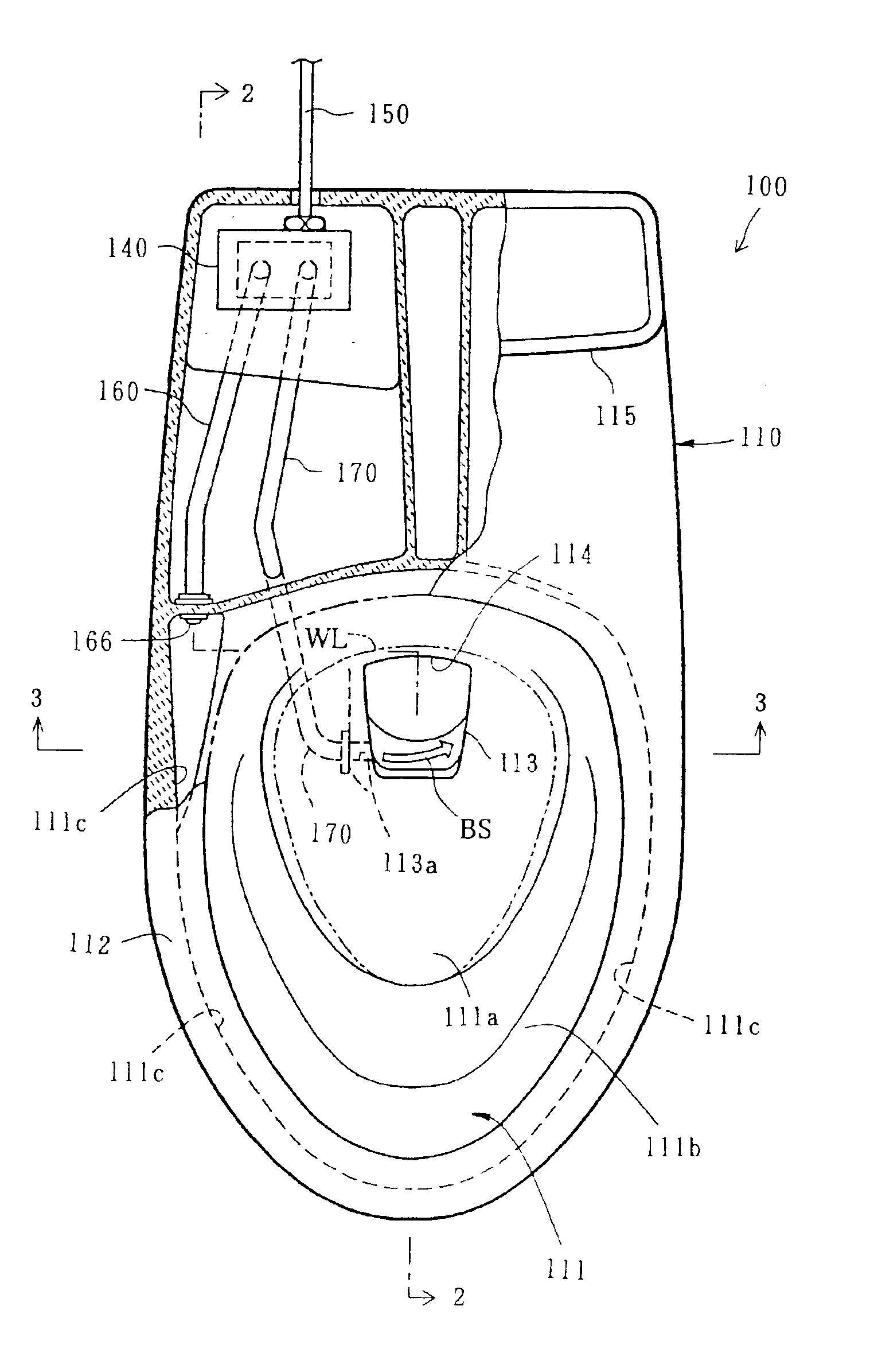
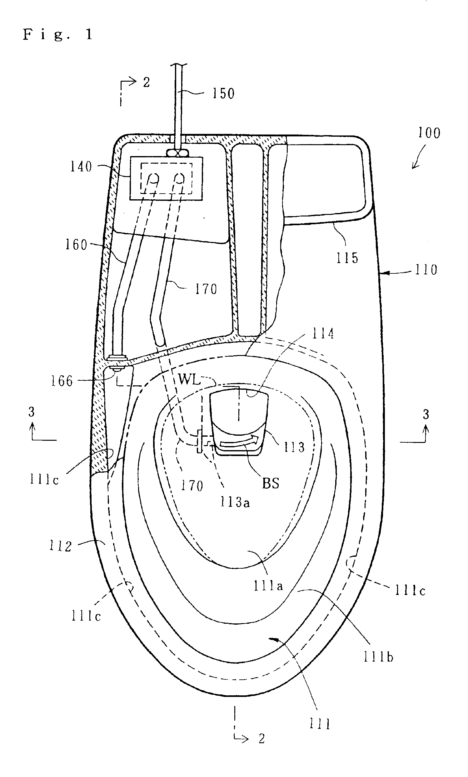
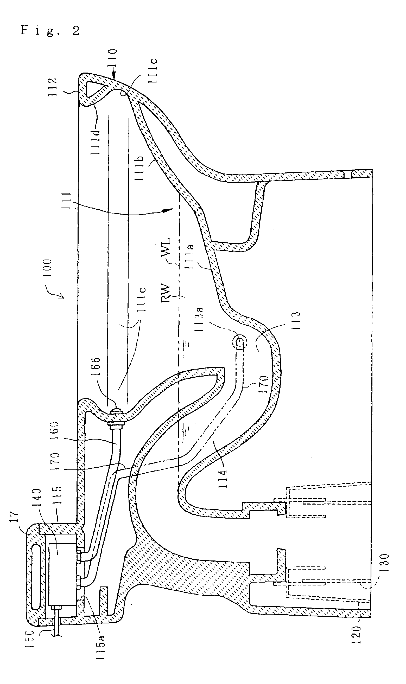
[0100]As shown in FIGS. 1 to 3, a flush toilet 100 in accordance with a first preferred embodiment of the present invention is provided with a toilet body 110 made of ceramic. The toilet body 110 is provided with a bowl 111. The bowl 111 forms a wet surface 111a contacting water seal RW at the lower part of its inner surface and a dry surface 111b not contacting the water seal RW at the upper part of its inner surface. The dry surface 111b is provided with an annulus concave 111c at its upper peripheral portion. The annulus concave 111c extends substantially horizontally. The bowl 111 forms an annulus rim at its upper end. An overhang 111d extends from the annulus concave 111c to the annulus rim 112.

[0101]The bowl 111 is provided with a concave 113 at its bottom. A trap-way 114 with reversed S shape extends rearward from a side of the concave 113. The trap-way 114 is conne...


PUM


Abstract

A flush toilet comprises a toilet body having a bowl for storing wash water as water seal, first means for supplying the toilet body with pressurized wash water and second means for discharging the wash water substantially horizontally along the upper peripheral portion of the inner surface of the bowl to swirl it along the inner surface of the bowl.

Description

TECHNICAL FIELD[0001]The present invention relates to a flush toilet provided with a toilet body having a bowl for storing wash water as water seal and a device for supplying the toilet body with pressurized wash water.BACKGROUND ART[0002]A flush toilet provided with a toilet body having a bowl for storing wash water as water seal and a device for supplying the toilet body with pressurized wash water, wherein wash water led from a tank directly connected to the toilet body discharges substantially horizontally along the upper peripheral portion of the inner surface of the bowl to swirl along the inner surface of the bowl is disclosed in International Laid-Open Publication WO98 / 16696. The aforementioned flush toilet has an advantage in that it does not cause loud noise during its operation because the wash water swirls and goes down along the inner surface of the bowl to run into the water seal aslant.[0003]The flush toilet disclosed in the International Laid-Open Publication WO98 / 16...

Claims


Application Information

Patent Timeline
IPC IPC(8): E03D11/08E03D1/28E03D3/06
CPCE03D1/28E03D3/06E03D11/08E03D2201/40E03D2201/30
Inventor HIDETAKA, MIYAHARASHOSAKU, NODANOBORU, SHIMBARASHINJI, SHIBATAMASAHIRO, SHINKAWANOBUSUKE, MATSUO
Owner TOTO LTD
Why Eureka
Try Eureka