Manual key miller

A pit pattern and key technology, which is applied in the field of key pit pattern planing machines, can solve the problems of metal chips flying out, complex structure, operation restrictions, etc., and achieve the effects of small space location, simple use method, and easy maintenance.

Inactive Publication Date: 2010-03-24
View PDF7 Cites 0 Cited by
  • Summary
  • Abstract
  • Description
  • Claims
  • Application Information

AI Technical Summary

Problems solved by technology

[0005] At present, the known key pit planer is usually electric type, its structure is more complicated and the operation is limited by the power supply, and because the motor of the electric key pit planer rotates at high speed, it will be accompanied by a large amount of metal chips flying at the same time. out, so very unsafe
Furthermore, the cost of the electric key pit planer is relatively high, the noise is relatively high during operation, and the tool needs to be replaced several times in each process

Method used


Image

  • Manual key miller
  • Manual key miller
  • Manual key miller

Examples


Embodiment Construction

[0021] Reference will now be made in detail to the preferred embodiments of the invention, examples of which are illustrated in the accompanying drawings. Wherever possible, the same reference numbers will be used throughout the drawings to refer to the same or like parts.

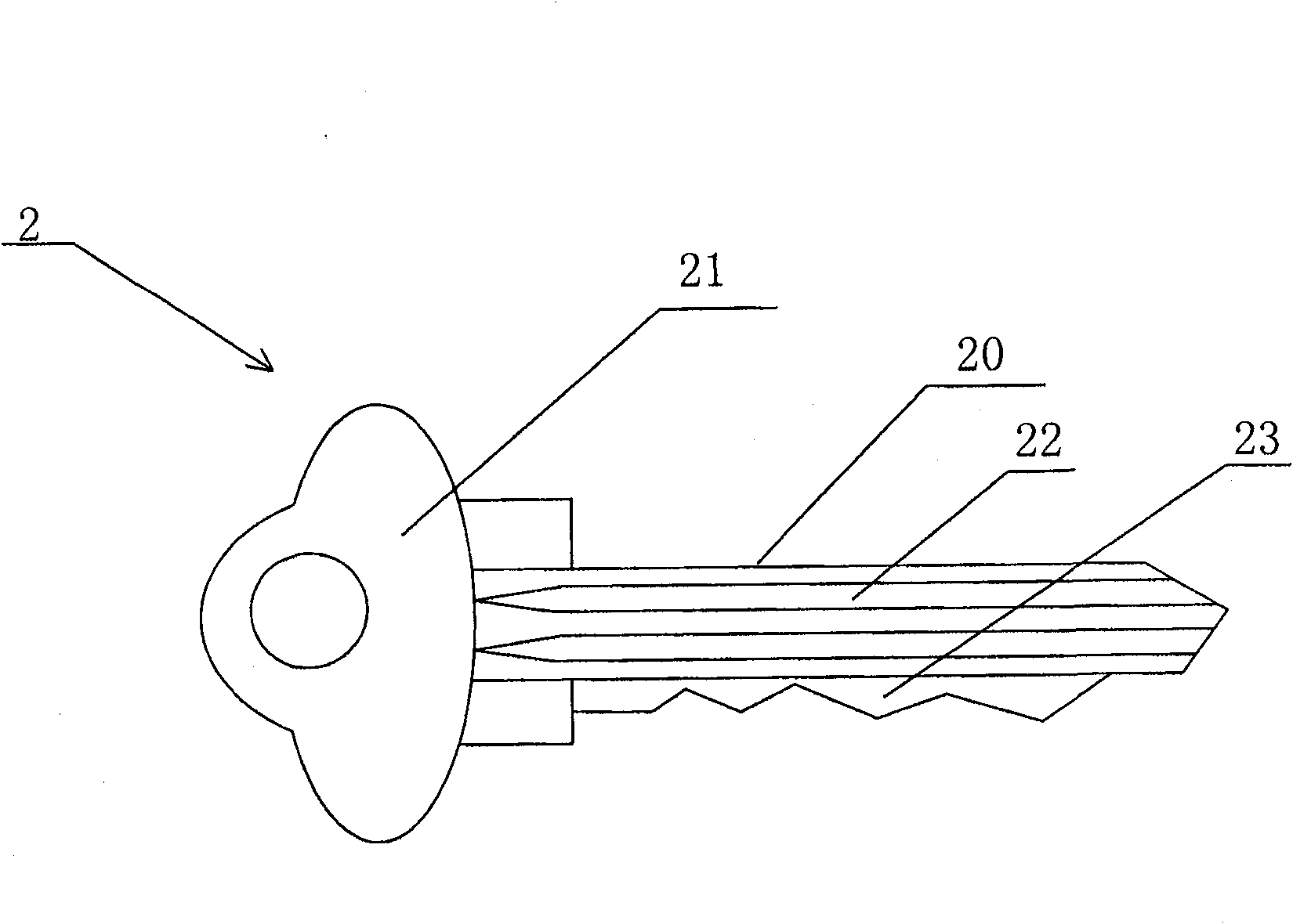
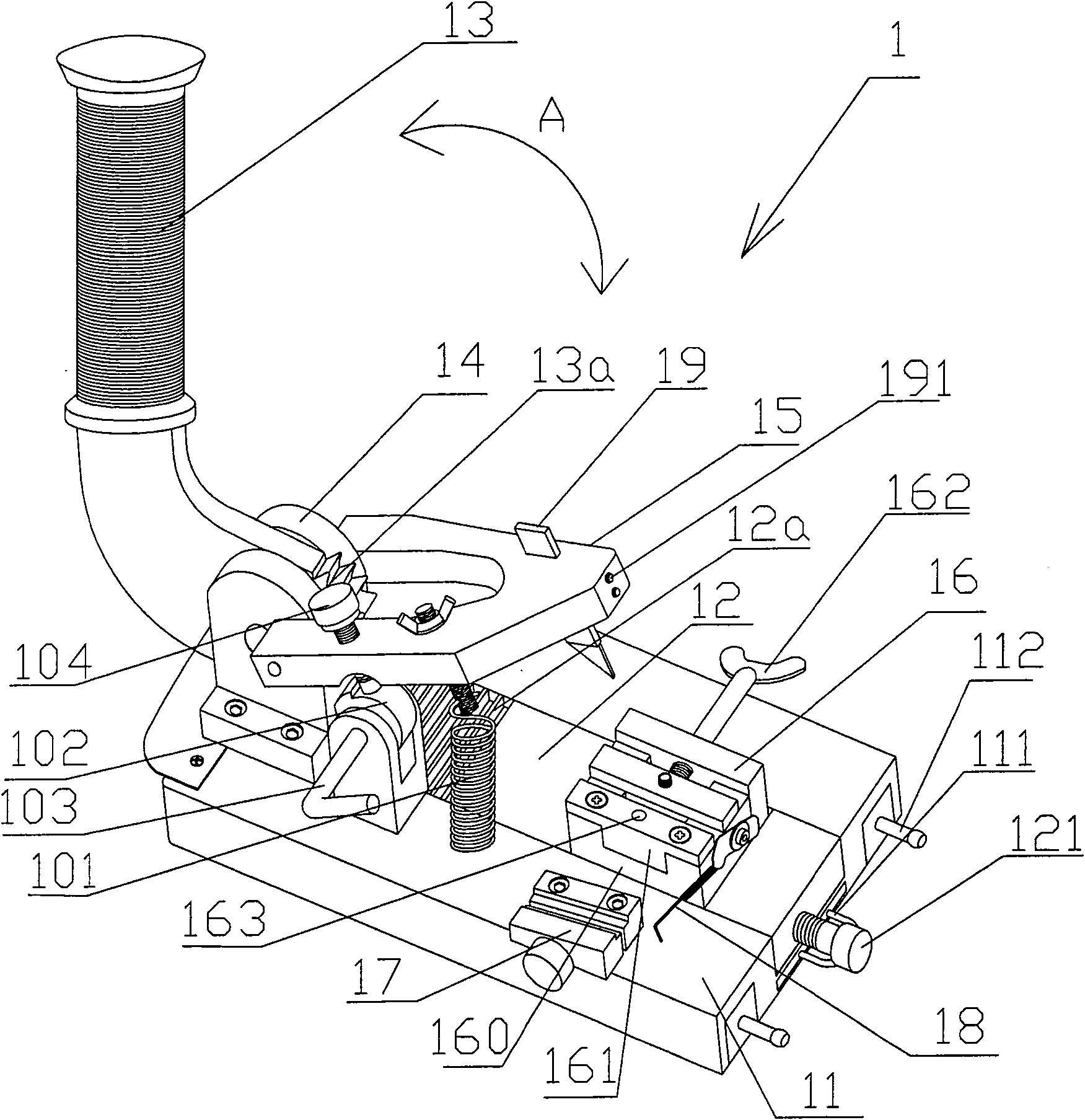
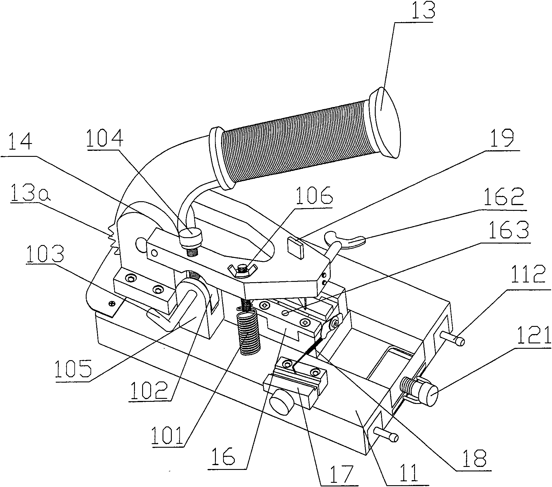
[0022] refer to figure 2 and image 3 , for illustrative purposes, the figure 2 and image 3 The direction toward the handle is defined as the rear, the direction opposite to the handle is defined as the front, and the direction perpendicular to the front-rear direction is defined as the left-right direction.

[0023] According to the embodiment of the present invention, the manual key pit pattern planer 1 is generally composed of a base 11, a tooth plate 12, a handle 13, a connecting bracket 14, a knife rest 15, a movable clamp 16, a fixed fixture 17 and a pit pattern position indicating needle 18. and so on.

[0024] The pedestal 11 is usually a cuboid seat body, and the weight is relatively large...


PUM


Abstract

The invention relates to a manual key dent planer which comprises: a base; a handle which is pivotally connected to a connecting support and the lower end of which is provided with a gear part, the rotation center of which coincides with that of the handle; a toothed plate which can move under the drive of the handle via the mesh between the toothed plate and the gear part; a movable clamp which is used for clamping a key billet; a fixing clamp which is used for clamping an original key; a tool head, which is arranged above the movable clamp and one end of which is rotatablely connected to theother end of the connecting support and provided with a planer tool; a tool head positioning mechanism which comprises a draught spring and a lifting device, with one end of the draught spring connected with the base and the other end connected to the tool head, and the lift system positioned between the base and the tool head and causing the tool head to rotate upward; and a dent position indicator probe, one end of which is connected to the movable clamp and the other end of which extends to the fixing clamp so as to determine the position of the dent in the key billet according to the position of the dent in the original key. The manual key dent planer of the invention has the advantages of simple structure, safe use and convenient operation.

Description

technical field [0001] The invention relates to a key pit planing machine, in particular to a machine capable of forming key pit patterns through manual operation. Background technique [0002] There are generally pit patterns on the keys commonly used at present. [0003] figure 1 It is a schematic diagram showing the position and shape of the dimples on the key. Such as figure 1 As shown, the key 2 includes a key body 20 and a key handle 21 , and the key body 20 is formed with grooves 22 and teeth 23 . [0004] figure 1 What is shown in is only a specific form of dimples, but actually different types of keys have dimples of different shapes and positions. Due to the wide variety of key styles on the market, it is impossible for craftsmen engaged in key preparation to have all types of key blanks. Therefore, when making keys, it is sometimes necessary to process and modify the pit patterns on the key blanks. [0005] At present, the known key pit planer is usually ele...

Claims


Application Information

Patent Timeline
Patent Type & Authority Patents(China)
IPC IPC(8): B23D9/00B23C3/35B21D53/42
Inventor 李从李从
Why Eureka
Try Eureka