Flush toilet

a technology for flushing toilets and toilets, applied in the field of flushing toilets, can solve the problems of unsolved noise problems, low water main pressure, and inability to use toilets in localities with low water main pressure, and achieve the effect of reducing the time up until the siphon action, reducing the volume of flushing water, and reducing the nois

Active Publication Date: 2009-12-24
TOTO LTD
View PDF16 Cites 32 Cited by
  • Summary
  • Abstract
  • Description
  • Claims
  • Application Information

AI Technical Summary

Benefits of technology

[0010]The present invention therefore has the object of providing a flush toilet which is not prone to the effects of water main pressure, has a reduced siphon cutoff sound when the siphon action stops, and satisfies the requirement for water conservation.
[0011]The present invention also has the object of providing a flush toilet capable of reducing the time required until the siphon action is generated, and of satisfying the requirement for water conservation.

Problems solved by technology

However, because the flush toilet set forth in Patent Document 1 supplies flush water to the toilet bowl portion using water main pressure alone, it cannot be used in localities with low water main pressure, or on the second or third floors of buildings and the like where water pressure is lower.
Also, in this type of flush toilet, after the siphon action ended a relatively large volume of air was sucked from the trap pipe producing an unpleasant gurgling sound as the siphon action was cut off.
In the flush toilet set forth in Patent Document 2, flush water stored in the tank is pressurized by a pump and expelled from a jet water spouting port, thus solving the problem of non-usability in low water pressure localities or sites, but the noise problem remained unsolved.
At the same time, as noted above, in the flush toilet of Patent Document 2 flush water is spouted from the jet water spouting port after spouting of flush water from the rim water spouting port is completed, but because the volume of jet spouted water is low, a long time is required until the siphon effect is generated (siphon start), increasing flush water volume by that amount, such that the water conservation requirement is not satisfied.

Method used


Image

  • Flush toilet
  • Flush toilet
  • Flush toilet

Examples


first embodiment

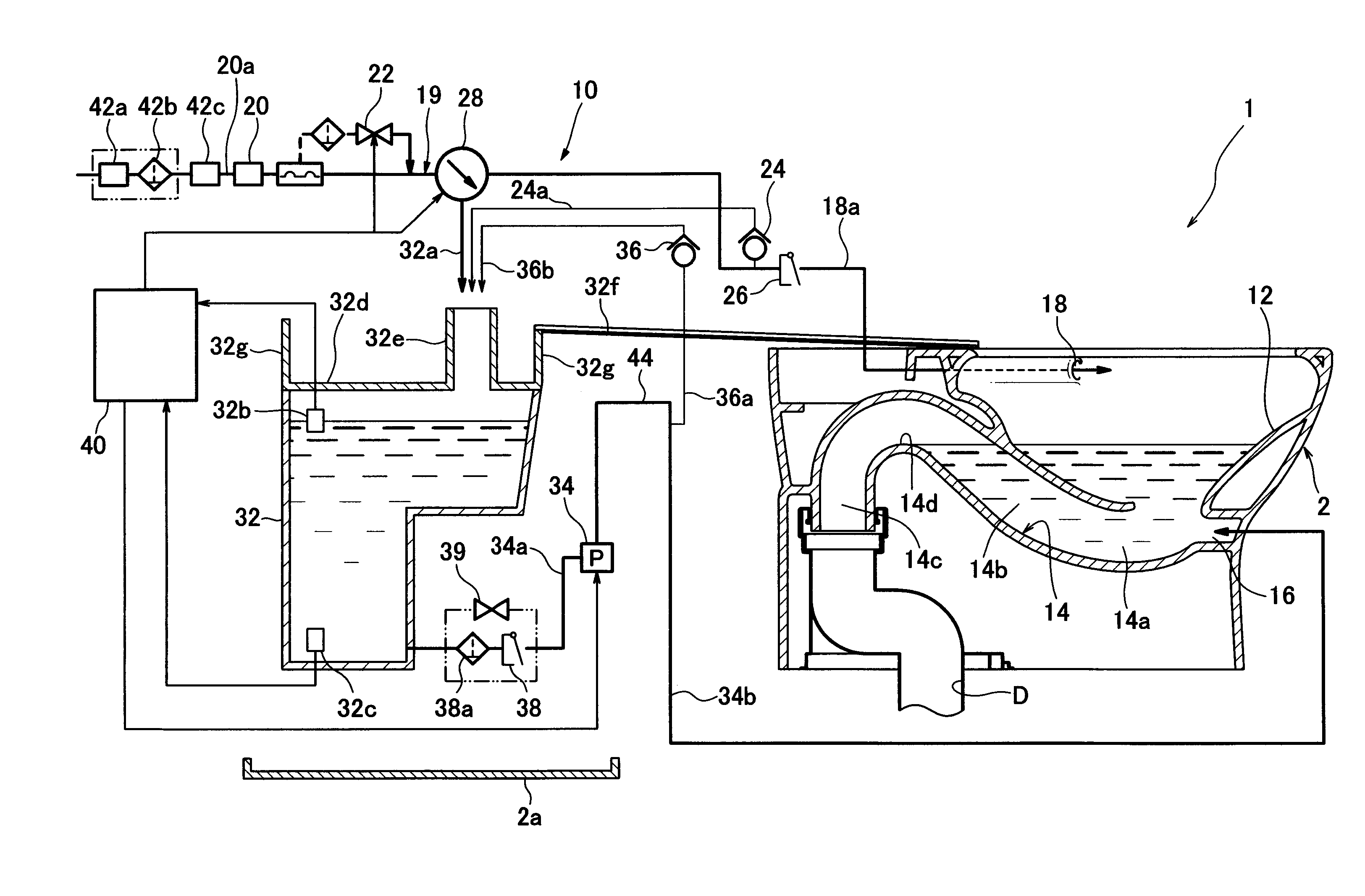
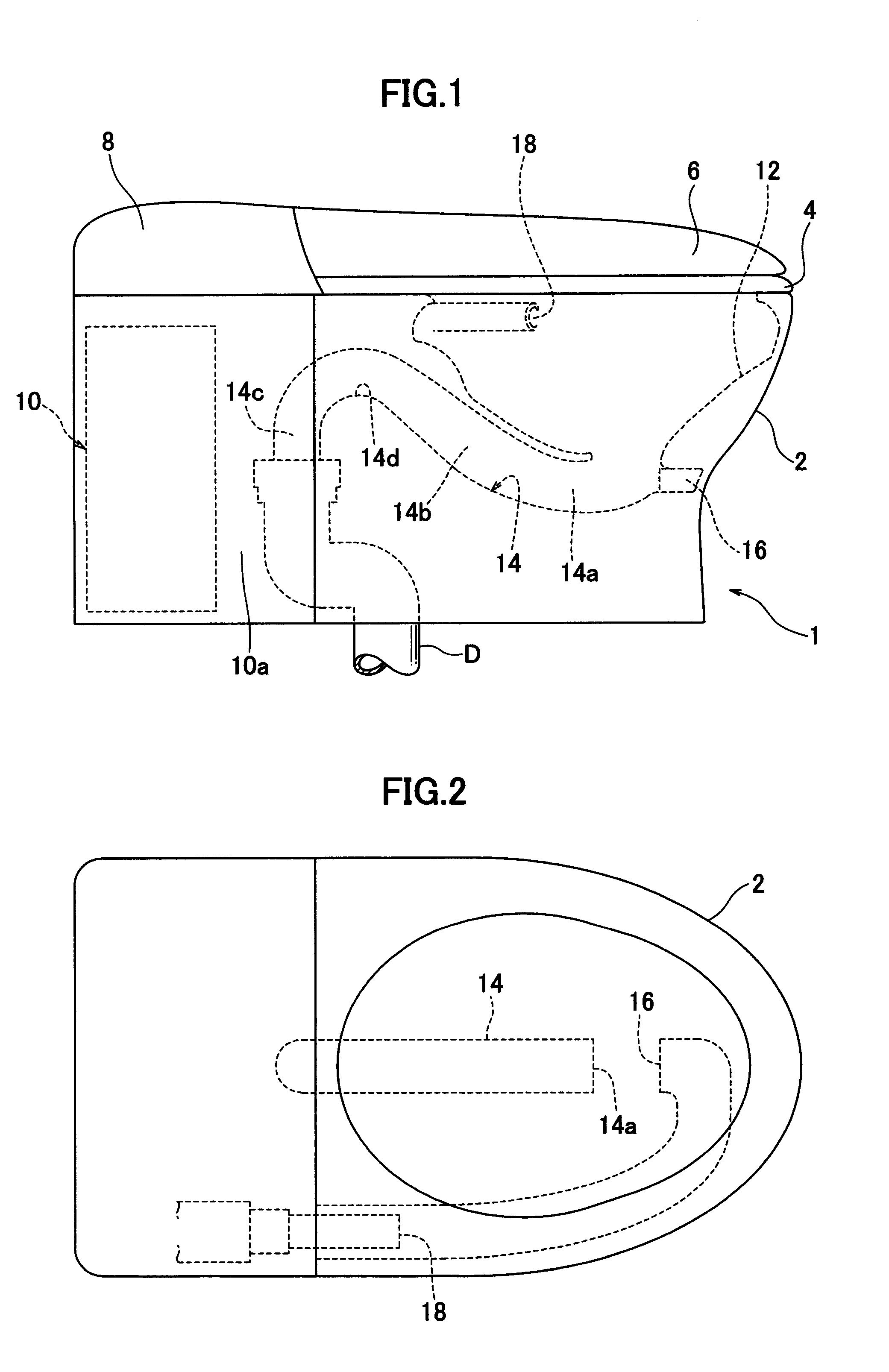
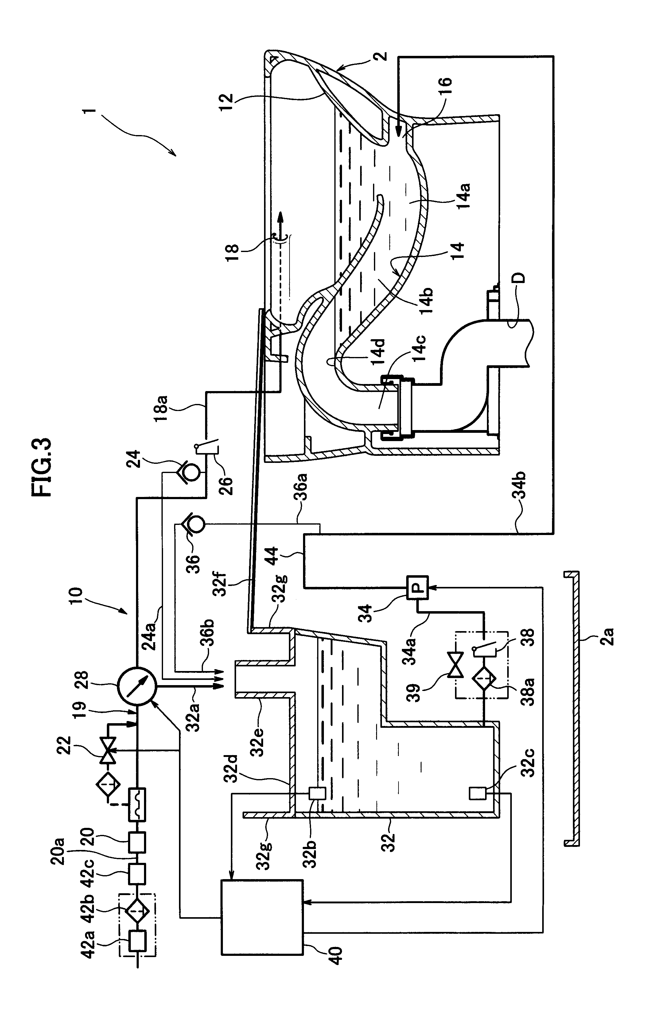
[0067]First the structure of a flush toilet according to the present invention will be described with reference to FIGS. 1 through 3. Here, FIG. 1 is a side elevation view showing a flush toilet according to the present invention; FIG. 2 is a plan view showing the flush toilet shown in FIG. 1, and FIG. 3 is a schematic overview showing the flush toilet shown in FIG. 1.

[0068]As shown in FIGS. 1 and 2, the flush toilet 1 according to the first embodiment of the present invention comprises a toilet main unit 2, a toilet seat 4 disposed on the upper surface of the toilet main unit 2, a cover 6 disposed so as to cover the toilet seat 4, and an outer flushing device 8 disposed at the rear upper portion of the toilet main unit 2. In addition, a functional portion 10 is disposed at the rear of the toilet main unit 2, and the functional portion 10 is covered by side panels 10a.

[0069]The toilet main unit 2 is ceramic, formed on the toilet main unit 2 are a bowl portion 12 for receiving waste...

third embodiment

[0096]Thereafter (time t3), the pressurizing force is slightly reduced by reducing the pump rpm down to N2, and flush water continues to be expelled from the jet water spouting port 16 at a large flow volume of less than 60 liters / minute-120 liters / minute (corresponding to the “first pattern” by “second flow volume” in the third embodiment discussed below). This allows the siphon action generated by the large flow volume of flush water expelled at a pump rpm of N2 by the “push-out action” discussed below to be continued even longer, thereby enabling the quick discharge of floating waste remaining in the bowl portion.

[0097]Moreover, the pump rpm N2 achieves the flow speed value necessary for the jet water spout to convey waste to the drain trap pipe 14 peak portion 14d (3.0 meter / second-6.2 meters / second).

[0098]Note that in the present embodiment, as shown by the dotted line in FIG. 4, the pump rpm can also be held as is at N1, without a reduction to N2 (time t3-t4).

[0099]In addition...

second embodiment

[0116]In the flush toilet the rim water spouting electromagnetic valve 23 and the tank water supply electromagnetic valve 25 can be independently opened and dosed, therefore as discussed below, rim water spouting and tank water supply can be carried out at the same timing.

[0117]Next, referring to FIG. 8, examples of timing for applicable rim water spouting (former rim flush and latter rim flush), jet water spouting (jet flush), and tank water supply in the first and second embodiments of the present invention will be explained (Ex. 1 through Ex. 5).

[0118]FIG. 8 shows the following examples, respectively: Ex. 1 in FIG. 8(a), Ex. 2 in FIG. 8(b), Ex. 3 in FIG. 8(c), Ex. 4 in FIG. 8(d), Ex. 5 in FIG. 8(e).

[0119]First, Ex. 1 in FIG. 8(a) is the same as what is shown in FIG. 4. In Ex. 1, former rim flushing is first performed for eight seconds, jet flushing is then performed for 2.9 seconds while supplying water to the tank is simultaneously performed for 2.9 seconds. Rim flushing is the...


PUM


Abstract

A flush toilet device has a toilet body having a bowl section, rim water discharge opening, a jet water discharge opening, and a discharge water trap conduit. A pressurizing pump is provided for pressurizing flush water contained in a cistern to supply it to the jet water discharge opening. A pump controller regulates the operation and rotation speed of the pressurizing pump to regulate the flow speed and flow rate of flush water discharged from the jet water discharge opening so that flush water at a first flow rate for generating a siphon effect is discharged and then at a second flow rate is discharged at the end of the siphon effect generated by the first flow rate. The second flow rate having a flow speed that can carry away human wastes and causes the siphon effect to continue by closing the cross section of any portion of the discharge water trap conduit.

Description

TECHNICAL FIELD [0001]The present invention relates to a flush toilet, and more particularly to a flush toilet cleaned by pressurized flush water.BACKGROUND ART [0002]Conventionally, flush toilets have been known in which, as set forth in Japanese Patent 2953002 (Patent Document 1), a direct connection is made to a water main, and without the use of a tank the bowl portion is flushed using water main pressure by supplying flush water from a rim water spouting port provided on the rim of a toilet bowl portion, and from a jet water spouting port provided on the bottom portion of the bowl portion, which spouts water toward a drain trap pipe.[0003]In addition, flush toilets have been known in which, as set forth in Patent Document 2, rim spouted water is directly supplied as water main water from a rim water spouting port, whereas jet spouted water is flush water stored in a tank and pressurized by a pump, with this pressurized flush water then being expelled from a jet water spouting p...

Claims


Application Information

Patent Timeline
Patent Type & Authority Applications(United States)
IPC IPC(8): E03D3/10
CPCE03D5/01E03D2201/30E03D11/08E03D5/00E03D11/02
Inventor OKUBO, MAYUUSHIJIMA, YOSHIKAZUSATO, YUICHIKATO, YOSHINOBUHAYASHI, RYOSUKESHIBATA, SHINJI
Owner TOTO LTD
Why Eureka
Try Eureka