Electric slow-stewing cooker

Inactive Publication Date: 2012-03-01
MIDEA GRP CO LTD
View PDF1 Cites 74 Cited by
  • Summary
  • Abstract
  • Description
  • Claims
  • Application Information

AI Technical Summary

Benefits of technology

[0009]The object of the present invention is to provide an elect

Problems solved by technology

An obvious shortcoming of such a design is that the relay is always in its working state and thus becomes

Method used


Image

  • Electric slow-stewing cooker
  • Electric slow-stewing cooker
  • Electric slow-stewing cooker

Examples


Embodiment Construction

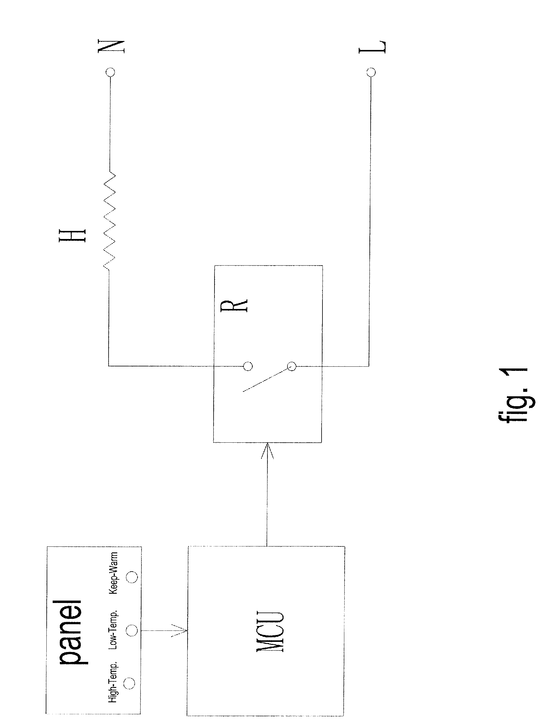
[0030]FIG. 1 shows one controlling scheme for heating in an electric slow-stewing cooker in the prior art. Such an electric slow-stewing cooker includes one heating element (H) and one relay switch (R), in which the relay switch controls electrical connection for high-temperature mode, low-temperature mode, and keep-warm mode. The disadvantage of such a design is that the relay switch is always in a work state.

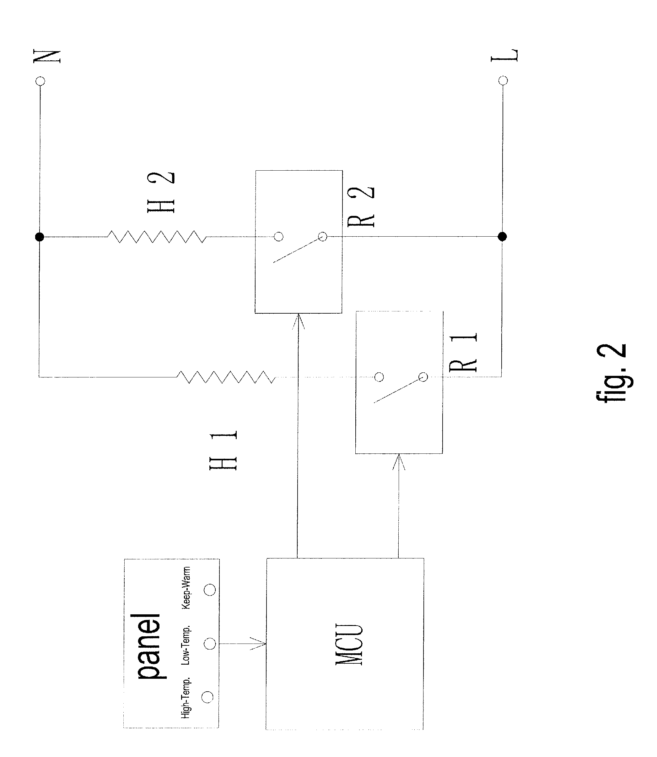
[0031]FIG. 2 shows another controlling scheme for heating in an electric slow-stewing cooker in the prior art with two relay switches (R1 and R2) and two heating elements (H1 and H2). The disadvantage of such a design is a relatively high cost.

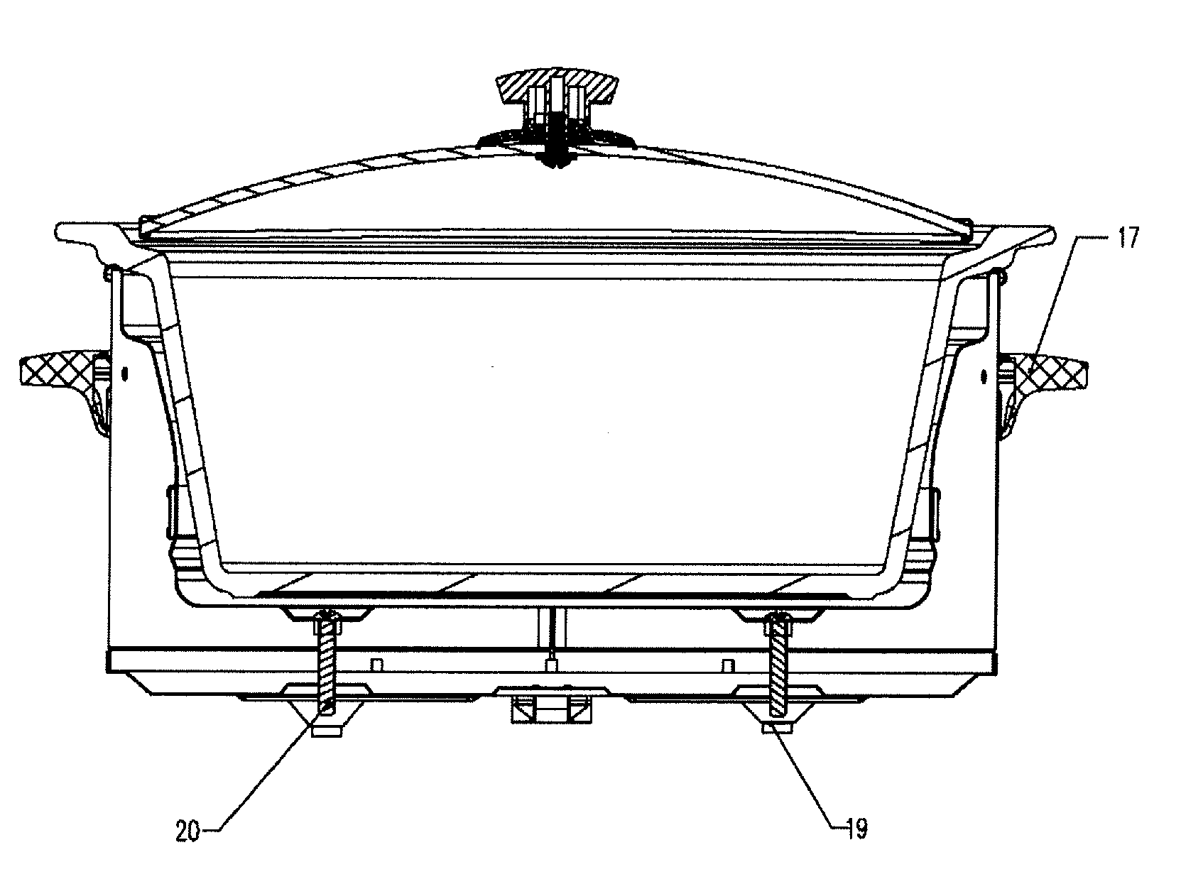
[0032]FIG. 3 shows the controlling scheme for heating in an electric slow-stewing cooker according to one embodiment of the present invention in which one relay switch (R) is used to control two heating elements (H1 and H2). FIG. 4 is a perspective view of an electric slow-stewing cooker according to one embodiment of the present inventi...


PUM


Abstract

The present invention discloses an electric slow-stewing cooker which has three heating modes, namely high-temperature mode, low-temperature mode and keep-warm mode. The electric slow-stewing cooker of the present invention comprises an upper cover, a cooking container, a barrel-like housing, a base, a control panel, heating elements, a control circuit board (PCB) and a manual switch used for controlling the heating elements, and a power supply unit. The heating elements are divided into two portions with one portion being electrically connected to the manual switch to perform the function of the keep-warm mode and the other portion being electrically connected to the control circuit board to perform the function of both the high-temperature mode and the low-temperature mode. At the present invention only one relay switch is required for the electric slow-stewing cooker, which will result in relatively low cost, and the most frequently used keep-warm mode is controlled by a manual switch, which will result in a high reliability.

Description

FIELD OF THE INVENTION[0001]The present invention relates to an electric slow-stewing cooker. More particularly the present invention relates to an electric slow-stewing cooker which can be controlled both by MCU and by manual switch.BACKGROUND OF THE INVENTION[0002]Slow-stewing cooker is a conventional kitchen ware, while electric slow-stewing cooker is a conventional home appliances. E.g. China patent application 200710156463.7 discloses an slow-stewing cooker, which comprises a housing, an aluminum container buckled on the upper chamber inside the housing, a ceramic container embedded inside the aluminum container, a heating circuit slipping over the bottom outside of the aluminum container, a temperature controller for controlling the temperature grade which is electrically connected to the heating circuit, a toggle switch with an indicator locating on the bottom outside of the housing which is electrically connected to the external power supply and the temperature controller. I...

Claims


Application Information

Patent Timeline
IPC IPC(8): H05B1/02
CPCA47J27/004
Inventor FENG, MINQIANGGAO, TIANBINGXING, FENGLEI
Owner MIDEA GRP CO LTD
Why Eureka
Try Eureka