

Foot pain-relieving articles and method thereof
a technology for foot pain and articles, applied in the field of foot pain relief, can solve the problems of current devices and methods for achieving such means that are not availabl
- Summary
- Abstract
- Description
- Claims
- Application Information
AI Technical Summary
Benefits of technology
Problems solved by technology
Method used
Image

Examples
Embodiment Construction
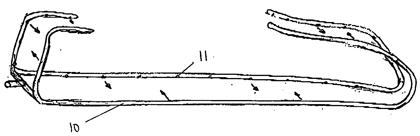
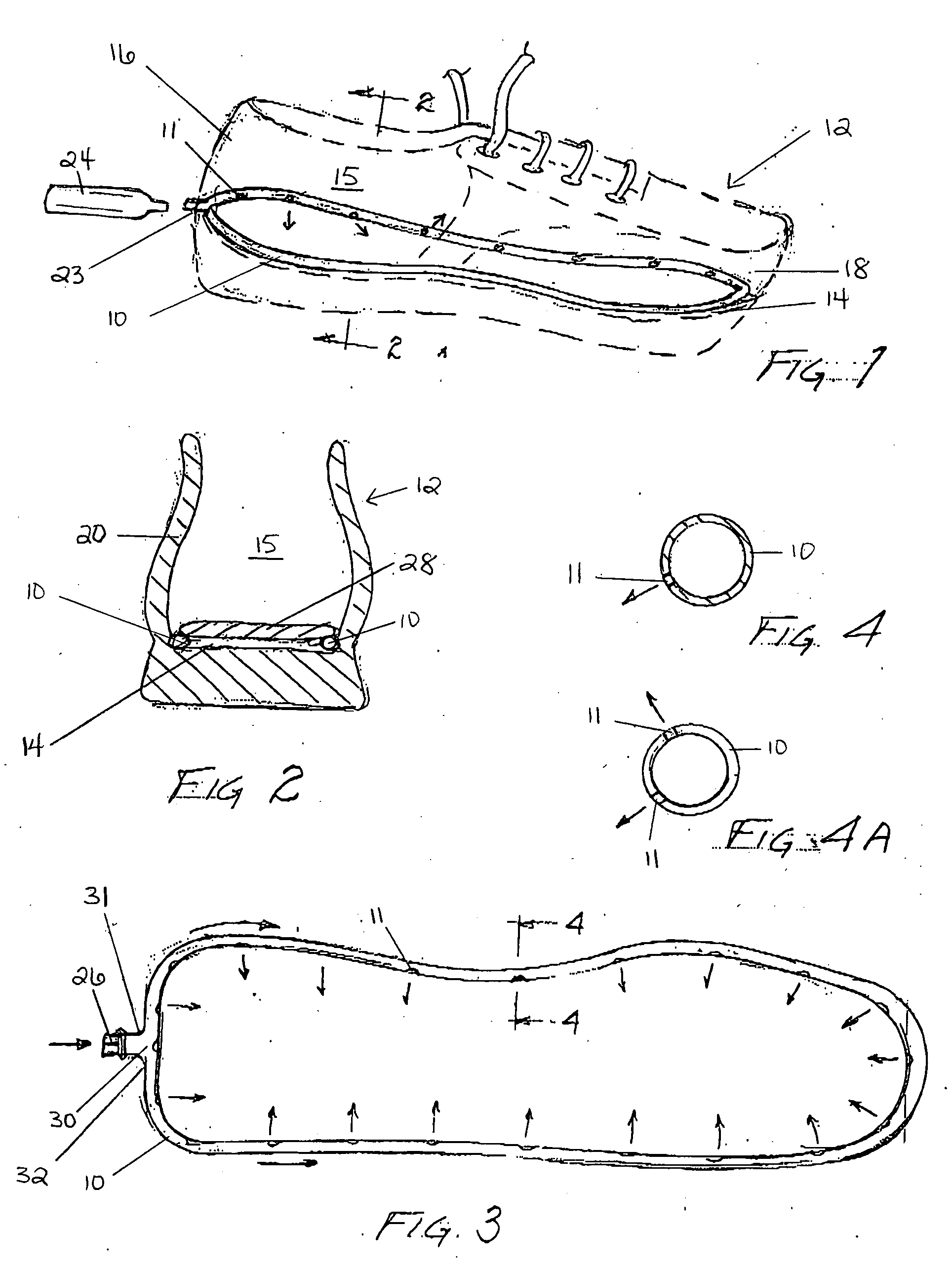
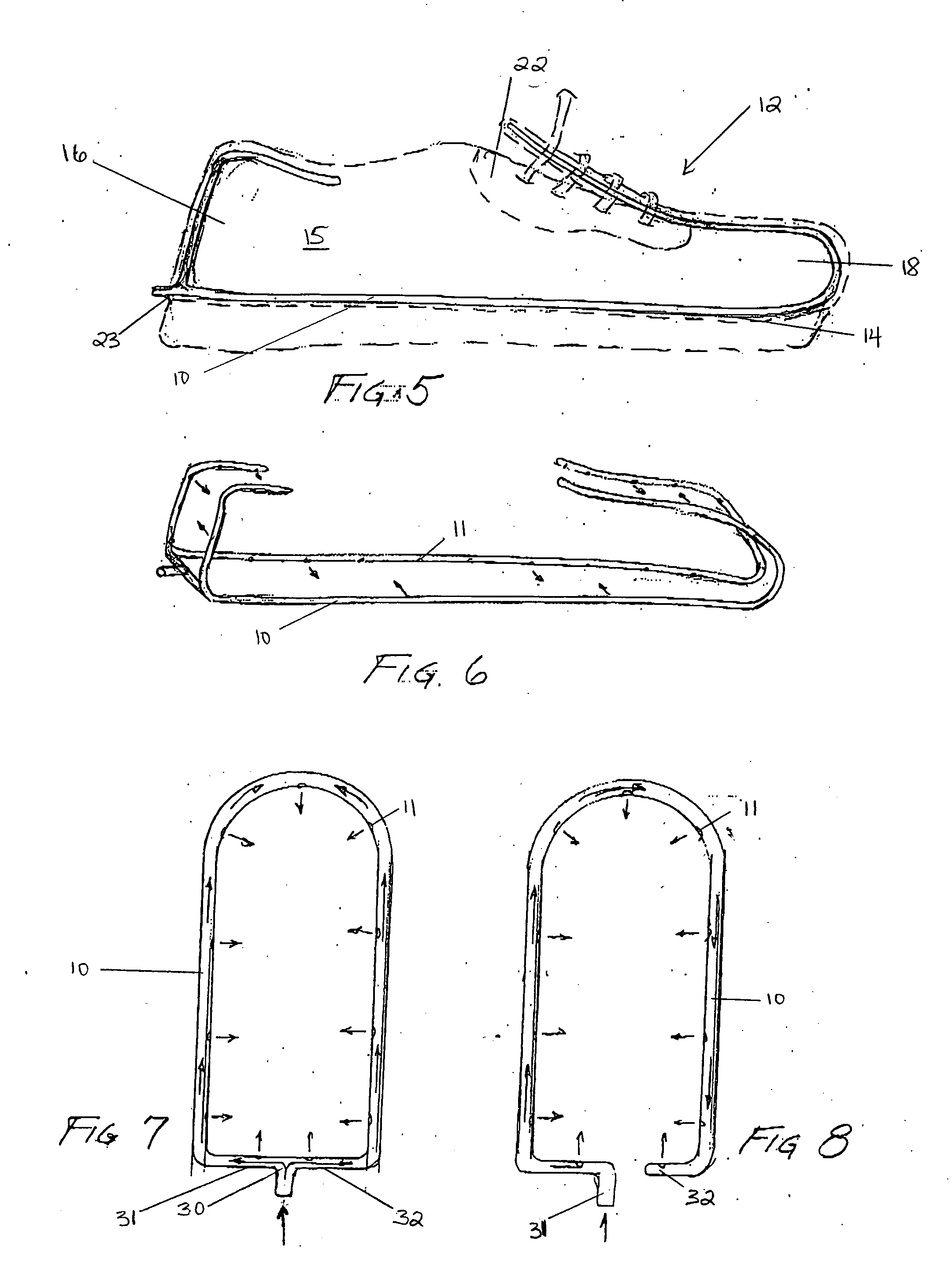
[0011] In accordance with one embodiment of this invention, a foot pain-relief article for footwear is disclosed. The foot pain-relief article comprises, in combination a footwear product, a length of tubing coupled to and extending along an insole of the footwear product, and a source of a gas fluid adapted to be introduced through an aperture in a portion of the footwear product into the tubing and adapted to be activated by a person for internally altering a temperature of the footwear product.
[0012] In accordance with a second embodiment, a method for providing foot pain-relief for a footwear product is disclosed. The method comprises the steps of providing a footwear product having a length of tubing coupled to and extending along at least a periphery of an insole of the footwear product, and providing a source of a gas fluid adapted to be introduced through an aperture in a rear portion of the footwear product into the tubing and adapted to be activated by a person for intern...
PUM
 Abstract
Description
Claims
Application Information