Mechanism for gas operated gun

a gas operated gun and mechanism technology, applied in the field of improved mechanism of gas operated guns, can solve the problems of high manufacturing and maintenance costs, increased gas use every day, and high cost of gas consumption

Inactive Publication Date: 2005-06-02
EIP MANAGEMENT
View PDF8 Cites 45 Cited by
  • Summary
  • Abstract
  • Description
  • Claims
  • Application Information

AI Technical Summary

Benefits of technology

[0006] A principal object of the present invention is to provide a simpler solution to the problem addressed by U.S. Pat. No. 5,613,483 allowing conventional paintball guns to have the advantages of the gun of that Patent as a result of a simple modification.

Problems solved by technology

A disadvantage of this otherwise simple arrangement is that more gas is used every time the gun is fired than is necessary to expel the selected paintball.
Consequently the source of compressed gas, usually an air cylinder fitted to the gun housing, has to be replaced quite frequently, which is an expense and inconvenience.
A drawback of this gun is its complexity and relatively high manufacturing and maintenance costs.

Method used


Image

  • Mechanism for gas operated gun
  • Mechanism for gas operated gun

Examples


Embodiment Construction

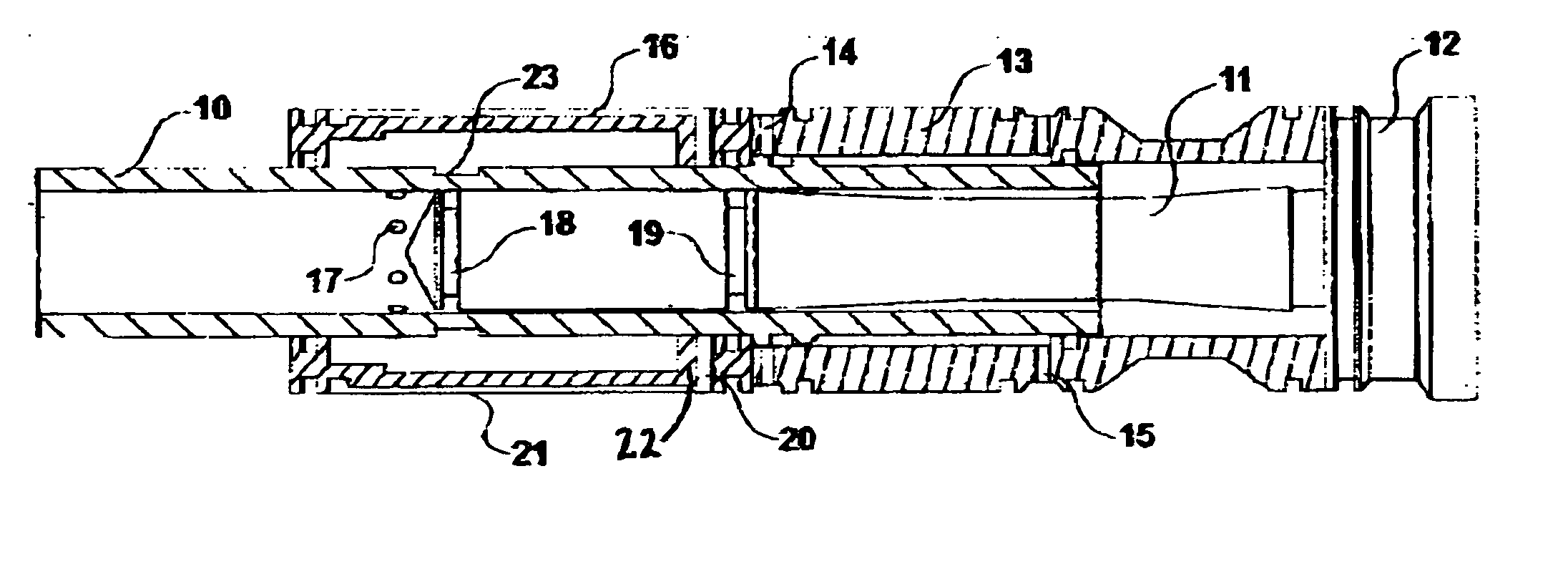
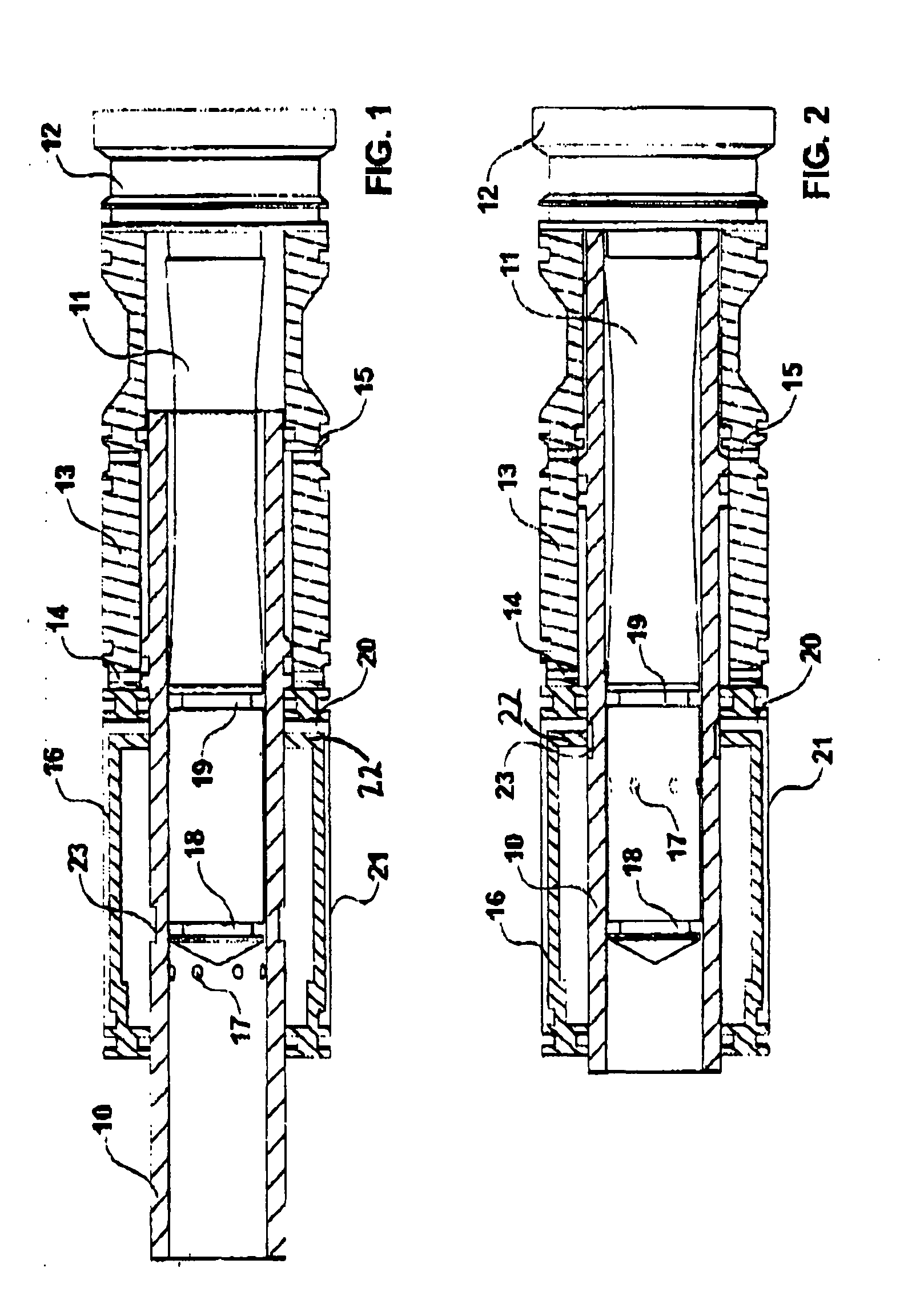
[0018] A paintball gun has a hollow, tubular bolt 10 which is slideable on a bolt guide 11 fixed cantilever fashion to the rear of the gun housing (not shown) by its head 12. Surrounding the bolt and bolt guide is a mechanism 13 which serves to move the bolt 10 forward when the trigger (not shown) of the gun is pulled and rearward when the trigger is released. In the example illustrated this mechanism 13 works by placing a compressed gas canister (not shown) fitted to the gun selectively in communication with bores 14 and 15 whereby lands on the bolt will be driven in one direction or the other. This arrangement is conventional and so will not be further described, except to say that compressed gas actuation of the bolt may be replaced by an electronic system.

[0019] Forward of the mechanism 13 a cylinder 16 surrounds the bolt and bolt guide. The cylinder extends beyond the distal end of the bolt guide 11 so that in the forward position of the bolt (FIG. 1) an array of circumferenti...


PUM


Abstract

A mechanism for a gas powered gun where a tubular bolt 10 of a paintball gun communicates with a cylinder 16 through bores 17 when in a forward, firing position, allowing compressed gas from the cylinder to expel a paintball. A port 20 whereby the cylinder communicates with a source of compressed gas is occluded by the bolt 10 except when a circumferential recess 23 in the bolt is in register with the port 20. By this arrangement only gas stored in the cylinder 16 is used to fire a paintball and the source of compressed gas is not in communication with the cylinder except when the trigger is released and the bolt 10 is withdrawn.

Description

[0001] This application is related to and claims priority from British application GB 0327683.9 filed Nov. 28, 2003. FIELD OF THE INVENTION [0002] This invention relates to an improved mechanism for a gas operated gun, by which is meant a gun of the type which fires a projectile by means of compressed gas. Guns of this kind are used in paintball games. Balls of paint are fired at other players to mark them. DESCRIPTION OF THE PRIOR ART [0003] Conventional paintball guns have a hollow bolt which, when the trigger is pulled to fire the gun, is moved from a rear to a forward position in the barrel, in the process selecting and moving forward the lowermost paintball in a magazine above the barrel. In the forward position of the bolt bores opening to its interior are exposed to compressed gas in a cylinder surrounding the bolt, causing the selected paintball to be expelled from the gun. When the trigger is released the bolt is moved back to its rear position, in which the bores are isola...

Claims


Application Information

Patent Timeline
Patent Type & Authority Applications(United States)
IPC IPC(8): F41B11/00F41B11/32F41B11/57F41B11/72F41B11/73
CPCF41B11/57F41B11/721F41B11/73F41B11/71
Inventor CARNALL, MARTINGARRY, PAUL
Owner EIP MANAGEMENT
Why Eureka
Try Eureka