
Mobile Terminated Communication Method and Related Devices

Active Publication Date: 2012-09-06
LG ELECTRONICS INC
View PDF31 Cites 152 Cited by
  • Summary
  • Abstract
  • Description
  • Claims
  • Application Information

AI Technical Summary

Benefits of technology

[0016]With the above mentioned features, the invention thus proposes a simple solution to the problem of sending messages to destination devices inside public or private IP address space. The solution avoids terminal complexity that was required in prior art (e.g. separate communication channel via SMS or IMS client), which makes it particularly suited e.g. to MTC devices (noting that it could also apply to non-MTC devices, like UEs or others).

Problems solved by technology

However, barring some special cases of limited interest (e.g. statically assigned public IP addresses), this is not sufficient for enabling mobile terminated communications, such as “push” type communications (i.e. communications initiated by a server in the network towards the mobile device) or peer-to-peer communications (e.g. communications between two mobile devices).
While both approaches are used today in 3GPP standards, they may not be suitable in certain cases because they put additional complexity on the device in the form of additional communication channel (e.g. SMS) or additional client software (e.g. IMS).
Moreover, both these approaches incur additional delay, which makes them less suitable for time critical delivery of mobile terminated messages.

Method used


Image

  • Mobile Terminated Communication Method and Related Devices
  • Mobile Terminated Communication Method and Related Devices
  • Mobile Terminated Communication Method and Related Devices

Examples


first embodiment

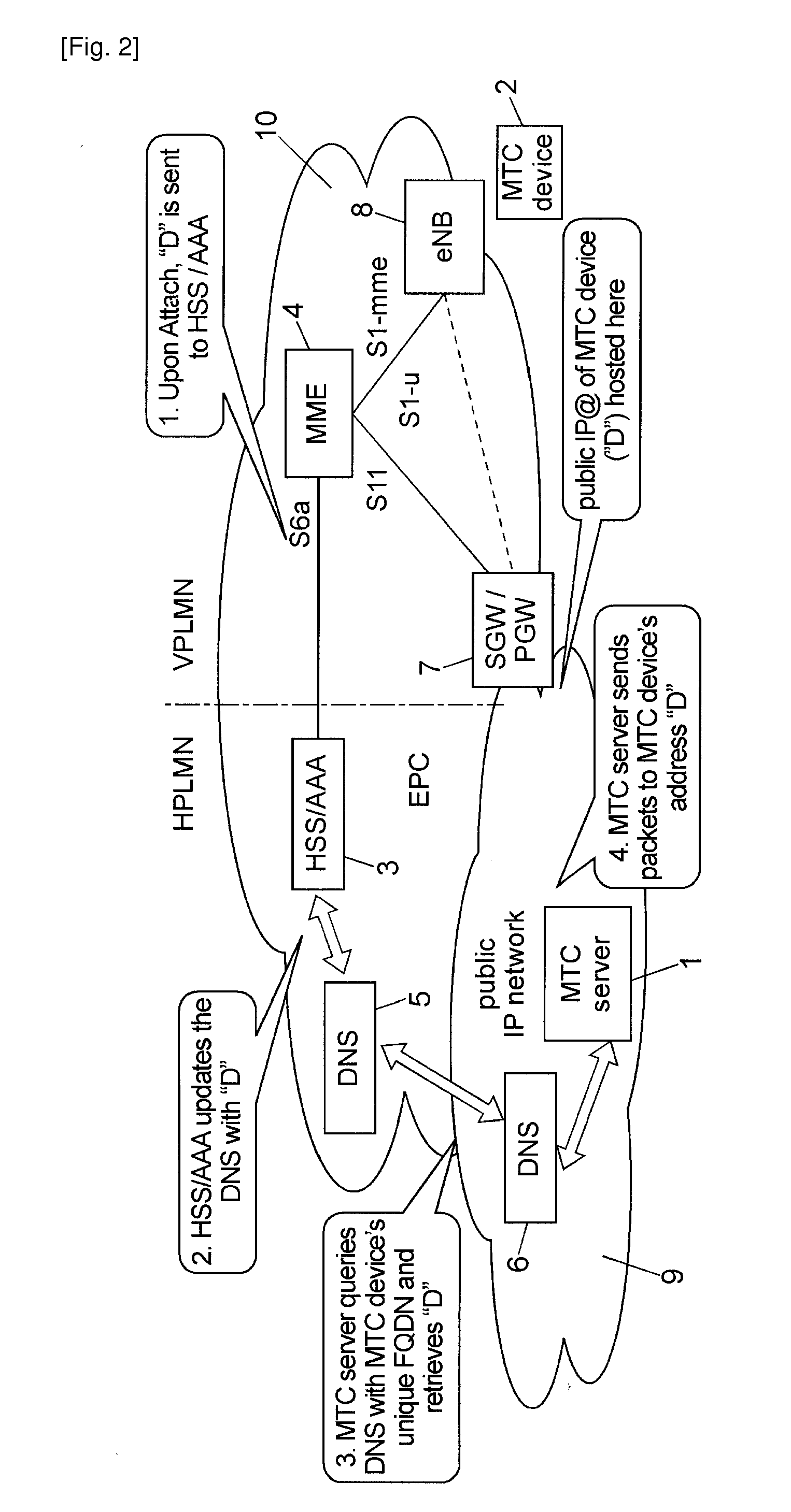
[0041]FIG. 2 shows an exemplary non-limiting MTC architecture in which the invention may take place according to a

[0042]In this example, a mobile terminated communication may take place from the MTC server 1 to the MTC device 2 through the EPS mobile communication network 10. It is assumed that the MTC device 2 is roaming in a visited network (VPLMN). Here, all the relevant EPS nodes are thus located in the VPLMN, except for the HSS / AAA node that resides in the Home network (HPLMN). So the mobile communication network 10 may be seen as the combination of HPLMN and VPLMN in the present example (or in other words, there are two mobile communication networks involved in this case). It should be noted however that the invention may take place alternatively in a single mobile communication network (e.g. a HPLMN without a VPLMN), for example if the MTC device 2 is not in a roaming situation.

[0043]Note also that the entities shown in FIG. 2 are the ones traditionally used in an LTE system....

second embodiment

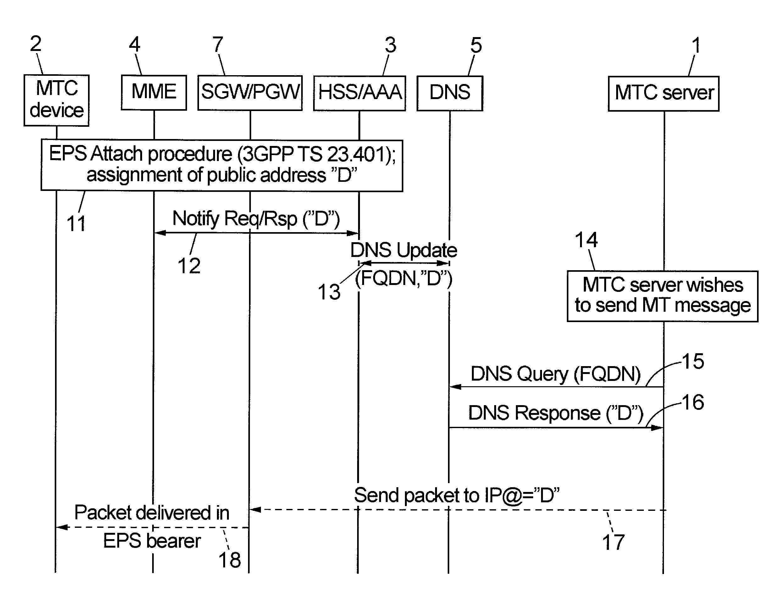
[0048]Upon attachment to the mobile communication network, or within the framework of any other appropriate procedure, the MTC device 2 that relies on IP communications is assigned an IP address. The latter is a public IP address in the present embodiment, which is advantageously dynamically assigned. Alternatively, the MTC device 2 may be assigned a private IP address, as will be discussed in a In roaming scenarios the dynamic IP address may be assigned in the Visited PLMN.

[0049]The association between the “host name” and the dynamically assigned (public) IP address is stored in the authoritative Domain Name System (DNS) server 5 in the Home PLMN.

[0050]When the MTC device 2 is assigned a dynamic (public) IP address, the authoritative DNS server 5 is kept up-to-date using DNS Update mechanisms.

[0051]The entity performing DNS updates is preferably, but not necessarily, located in the Home PLMN in order to reduce the number of trusted interfaces to the DNS server 5.

[0052]With referen...


PUM


Abstract

Method for allowing a mobile terminated communication to a destination device (2) through at least one mobile communication network (10) from a source entity (1) located in a public IP address network (9). The method comprises: a subscriber server (3) of the mobile communication network receiving an IP address (“D”) of the destination device from a node (4) of the mobile communication network, and the subscriber server updating a DNS record containing a static unique identifier of the destination device stored in an authoritative DNS server (5) reachable via the public IP address network, with said destination device IP address.

Description

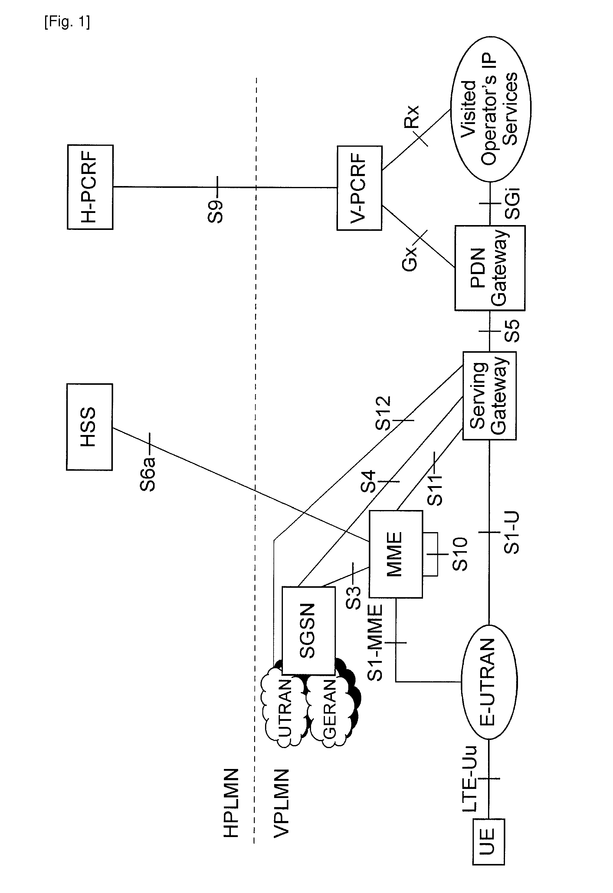
TECHNICAL FIELD[0001]The present invention relates to mobile terminated communication.BACKGROUND ART[0002]Mobile terminated communication from a source entity (calling party) to a destination device (called party) in a mobile communication system can be performed easily when the source entity knows an identifier of the destination device with which the destination device can be reached, such as a phone number.[0003]There are situations however where the identifier with which the destination device can be reached is not known by the source entity.[0004]Let us take the non-limiting example of the Evolved Packet System (EPS) architecture as defined in 3GPP TR 23.401 (GPRS enhancements for E-UTRAN access). In the EPS architecture, the Evolved Packet Core (EPC) network exists in several flavours. Depicted in FIG. 1 is the roaming EPC architecture with Local Breakout, which basically means that the IP address and the services in this configuration are provided by the Visited network. The ...

Claims


Application Information

Patent Timeline
IPC IPC(8): H04W8/26
CPCH04L29/12066H04L29/12188H04L29/1249H04L29/12575H04L29/12669H04L29/12905H04W76/021H04L61/1588H04L61/256H04L61/2592H04L61/304H04L61/6054H04W8/26H04L61/1511H04W76/11H04L61/4511H04L61/4588H04L2101/33H04L2101/654H04L12/28
Inventor STOJANOVSKI, SASOVEDRINE, ARNAUD
Owner LG ELECTRONICS INC
Learn More