Network managed device installation and provisioning technique

a network managed device and network management technology, applied in the field of communication components, can solve problems such as the need for timely response, and achieve the effect of reducing the volume of data traffi

Inactive Publication Date: 2005-06-30
PANDUIT
View PDF99 Cites 123 Cited by
  • Summary
  • Abstract
  • Description
  • Claims
  • Application Information

AI Technical Summary

Benefits of technology

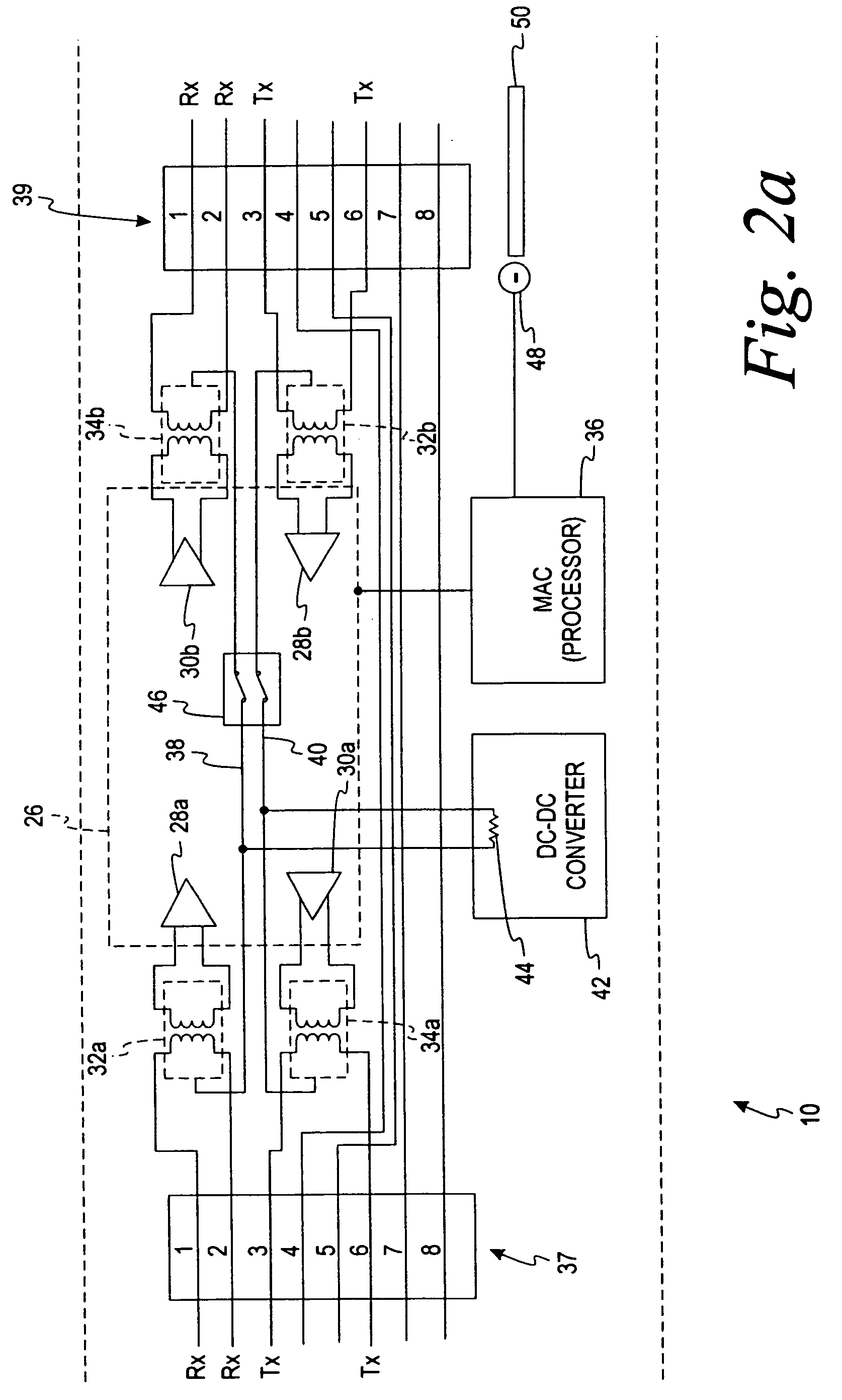
[0009] According to one embodiment of the present invention, the active jack is an electronic element that requires a source of DC power which can be obtained from Power Supplying Equipment (PSE) such as an IEEE 802.3AF compliant source. Such sources are deployed in networks as the source of DC power for an attached powered device (PD) such as a VOIP telephone that receives power according to a power-over-network scheme. According to some embodiments of the present invention, the power consumption of the active jack is minimal, with the remaining power forwarded to a powered device (PD) if one is connected.
[0010] There are several methods of supplying the active jacks with DC power. According to one embodiment of the present invention, PSE equipment such as an Ethernet switch or IP router is used. According to another embodiment a patch panel or mid-span patch panel can be used. When a patch panel is equipped with active jacks, a managed structure cable PSE system is obtained. The scope of management that a patch panel has can be enhanced if an active jack is used between the patch panel and the end device.
[0011] Current methods of cable plant management and security rely on having the state of the horizontal cable system and / or patch panels remain fairly constant. Further, if changes occur it is required that they are well documented and manually entered in the security / management system database. According to one embodiment of the present invention, use of active jacks facilitates monitoring the state of the patch cords and the horizontal cable system to provide a managed, structured cable system. If there is a removal or movement of a particular cable, the active jacks connected by the cable will lose upstream network connection. An active jack in a patch panel can detect the change periodically, for example, via once-per-second “heart beat” IP transmissions to the upstream switch. Because the PSE and PD communicate, the PSE can instantaneously report opens in the patch cord. Optionally, an active jack can send a message to a neighboring active jack to report communication problems. When the connection is re-attached, the active jack may send out an ARP message to indicate that it is back on line with any other devices connected to it. As the connection is re-established the switch port to the patch panel port is thus identified, an important aspect to managing the patch cord connectivity. Since the physical location information can be associated with active jacks, even momentary changes to the cable plant may be recognized and logged.
[0012] Since the active wall jack is a managed network element, remote visibility is gained by the management and operations components of a communications network. The active jack provides for remote monitoring, obviating or reducing the need to send out a technician to determine the state of the equipment. Service, can be remotely suspended or re-instated. Furthermore, end point devices which connect to a network using active jacks can be inventoried and controlled as well.
[0014] To support lifeline VOIP, PSE switches may be used to ensure that all the enterprise switches have enough DC power to survive an AC outage. The internal switches will continue to direct and manage VOIP calls to the outside world but deny other IP data transactions. According to one embodiment of the present invention, an advantage of the power patch panel with the active jack is that it can allow the upstream switches to power down during an AC power outage. The traffic can then be directed to a “lifeline” VOIP gateway from the patch panel, with the lifeline VOIP gateway supporting voice traffic and / or a reduced volume of data traffic.

Problems solved by technology

Issues with documenting and managing LANs have likewise increased the need for timely response when connectivity problems arise.
This has largely been due to the regulatory requirements on telephone service to supply life line capability and electrical issues such as a relatively high DC ring-tone voltage.

Method used


Image

  • Network managed device installation and provisioning technique
  • Network managed device installation and provisioning technique
  • Network managed device installation and provisioning technique

Examples


Embodiment Construction

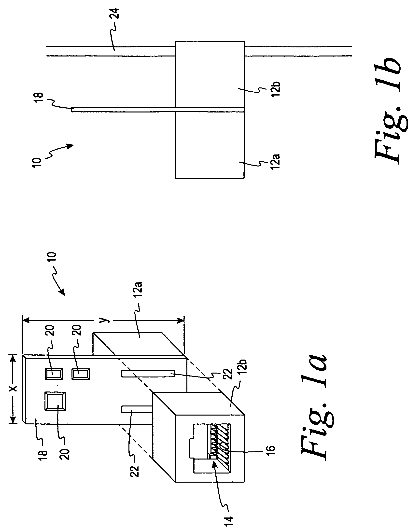
[0043] Referring now to the drawings, and initially to FIG. 1a, an isometric construction view of an active jack 10 is shown. The active jack 10 comprises two housings 12a and 12b which can form plug receiving openings 14 as shown in the drawing for the housing 12b. According to an alternative embodiment of the present invention, one connector of the active jack 10 is a pug and the other connector is an insulation displacement connector (IDC). The housings 12a and 12b may be of a type used for communication connectors as described more fully in U.S. Pat. No. 6,371,793, “Low Crosstalk Modular Communication Connector,” by Doorhy et al., issued Apr. 16, 2002 which is incorporated herein in its entirety by reference. Mounted within the plug receiving opening are a plurality of conductors 16 which form a resilient contact with a communications plug when the plug is connected to the active jack 10. The conductors 16 are led through the housing of the active jack 10 to make contact with th...


PUM


Abstract

A system for managing and documenting a local area communications network is provided which deploys power sourcing equipment and powered devices by the use of active electronic modules, having an Ethernet controller and Power over Ethernet forwarding capabilities, as integral, managed components within the cable plant, to enhance management, documentation, security and emergency 911 aspects of the network as well as extending the physical reach of the network.

Description

CROSS-REFERENCE TO RELATED APPLICATION [0001] This application claims the benefit of U.S. Provisional Patent Application Ser. No. 60 / 492,822, filed Aug. 6, 2003 and entitled “Network Managed Device Installation and Provisioning Technique.”INCORPORATION BY REFERENCE [0002] U.S. Provisional Application No. 60 / 492,822 filed Aug. 6, 2003 and entitled “Network Managed Device Installation and Provisioning Technique,” application Ser. No. 10 / 353,640, filed Jan. 29, 2003 and entitled “Systems and Methods for Documenting Networks With Electronic Modules,” U.S. Provisional Application No. 60 / 352,826, filed Jan. 30, 2002, application Ser. No. 10 / 366,093, filed Feb. 13, 2003 and entitled “VOIP Telephone Location System,” and U.S. Provisional Application No. 60 / 357,017, filed Feb. 14, 2002 are hereby incorporated by reference into the present application in their entireties.FIELD OF THE INVENTION [0003] This invention is directed generally to communications components and more specifically is di...

Claims


Application Information

Patent Timeline
Patent Type & Authority Applications(United States)
IPC IPC(8): H04L12/24H04L12/26
CPCH04L12/24H04L12/2697H04L43/50H04L41/22H04L43/0817H04L41/00
Inventor CAVENEY, JACK E.NORDIN, RONALD A.DOORHY, MICHAEL V.KOZICKI, KENNETH C.CONNEELY, RICHARD J.BOLOURI-SARANSAR, MASUDJACKS, STEVEN A.TISON, JACK D.LESHIN, BRIAN D.FARRIMOND, ELIZABETHFARRIMOND, ALAN
Owner PANDUIT
Why Eureka
Try Eureka