Wireless communication circuit

a wireless communication and wireless technology, applied in the field of geologic formation analysis, can solve the problem that the test cannot afford real-time data acquisition, and achieve the effect of maximizing the amplitude swing of the signal produced across the antenna and reducing power consumption

Active Publication Date: 2007-01-02
SCHLUMBERGER TECH CORP
View PDF30 Cites 48 Cited by
  • Summary
  • Abstract
  • Description
  • Claims
  • Application Information

AI Technical Summary

Benefits of technology

[0006]The invention includes a communication circuit and a method of communicating with wireless signals that features providing a tank circuit having an inductor connected in parallel with a capacitor circuit. The inductor is the antenna of the communication circuit and, therefore, always operates in resonance, even when the tank circuit components change with temperature. The antenna can, therefore, operate at a high Q with minimal power consumption when transmitting. The capacitor circuit includes a pair of capacitors coupled in series. Each of the capacitors is connected in common to ground and has a capacitive value associated. A feedback network is connected to selectively bias the tank circuit to produce a signal, while minimizing the power required to produce the signal. The feedback circuit operates to maximize the amplitude swing of the signal produced across the antenna. The single ended amplitude of the signal on each side of the antenna is a function of a ratio of the capacitive values associated with the capacitor circuit, with the frequency of the signal being defined by the inductor and the capacitor circuit. The tank circuit is multifunctional in that it may be biased to function as a transmitter and / or a receiver. Additionally, the tank circuit may be augmented with additional circuits that more clearly define the transmission or reception frequency, as well as to provide a remote power source for the same. These and other embodiments are discussed more fully below.

Problems solved by technology

However, these tests do not afford real-time data acquisition, because it is required to perform the tests once the drilling equipment has been removed from the hole, referred to as a trip.

Method used


Image

  • Wireless communication circuit
  • Wireless communication circuit
  • Wireless communication circuit

Examples


Embodiment Construction

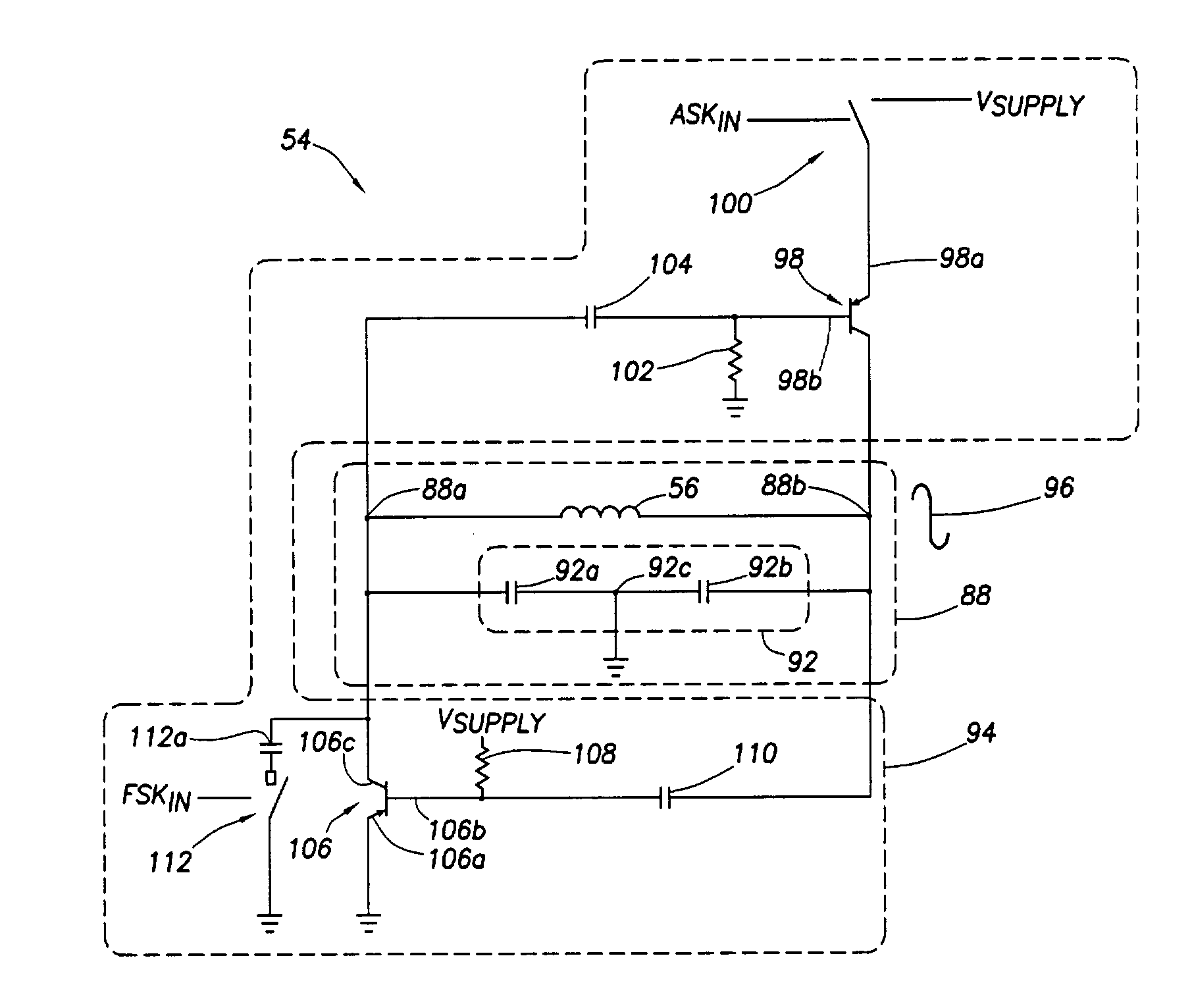
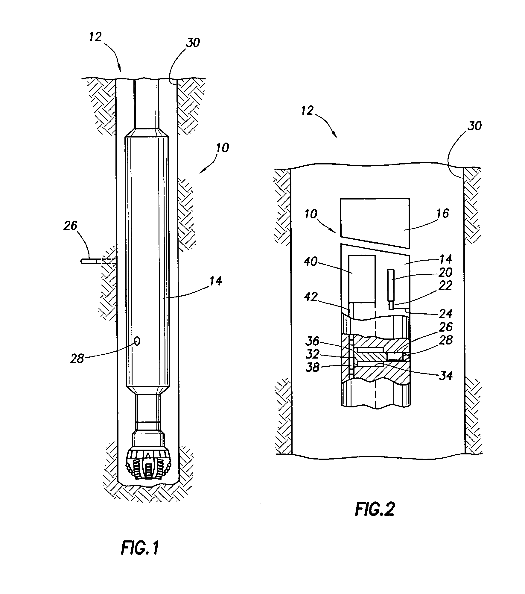
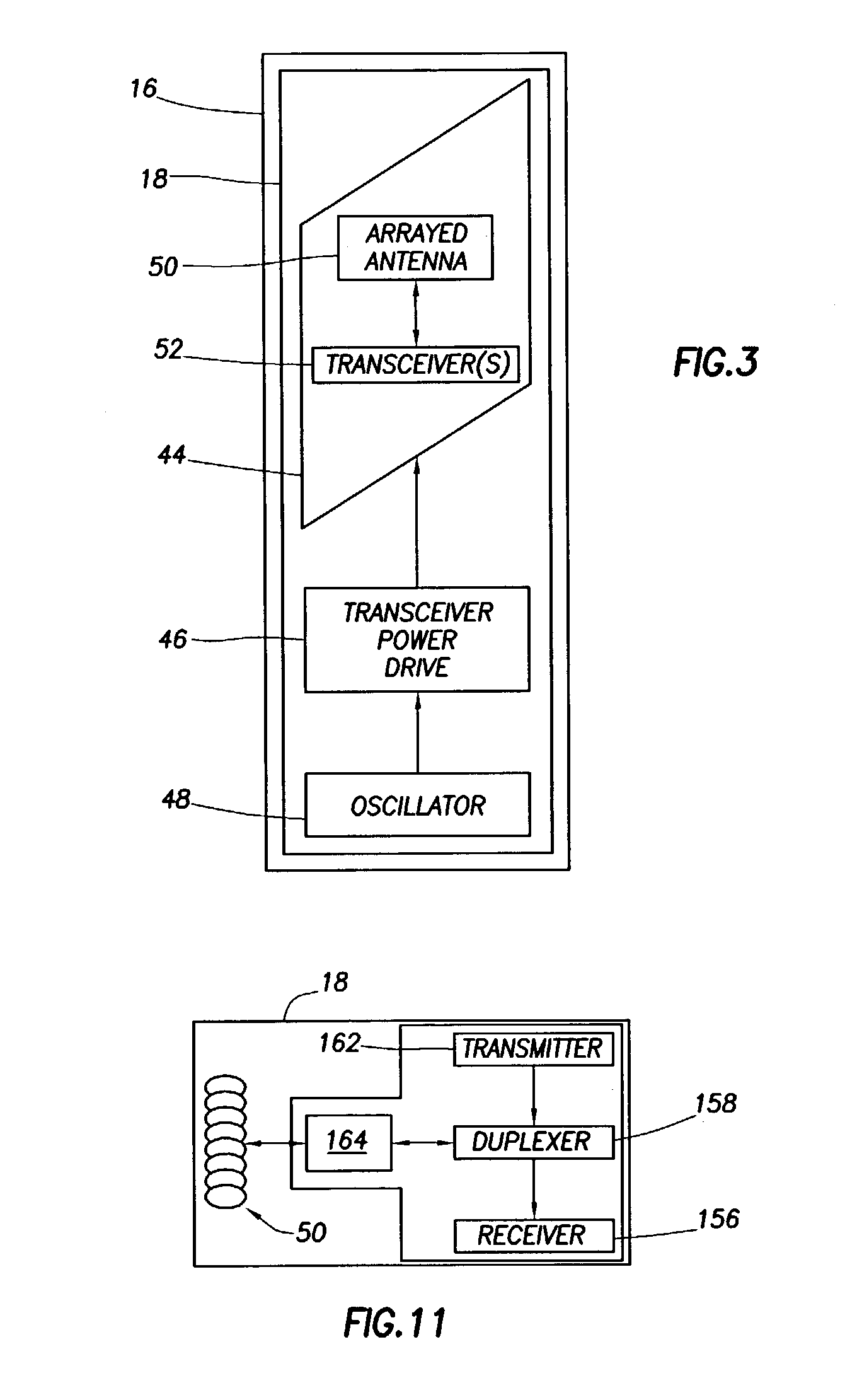
[0018]Referring to FIG. 1, an exemplary use of the present invention involves a drill collar 10 that includes a drill string (not shown) for drilling a well bore 12. Drill collar 10 is provided with a sonde section 14 including a data acquisition circuit 16, shown in FIG. 2, incorporating transmitter / receiver circuitry 18 of FIG. 3.

[0019]Referring to FIG. 2, drill collar 10 includes a pressure gauge 20 whose pressure sensor 22 is exposed to borehole pressure in well bore 12 via a drill collar passage 24. Pressure gauge 20 senses ambient pressure at the depth of a selected sub-surface formation and is used to verify pressure calibration of remote sensors. Electronic signals (not shown) representing ambient well bore pressure are transmitted via pressure gauge 20 to the circuitry of data acquisition circuit 16. Data acquisition circuit 16 then performs a pressure calibration of a remote sensor 26, shown best in FIG. 1, being deployed at that particular well bore depth.

[0020]Drill coll...


PUM


Abstract

The invention includes a wireless communication circuit and a method of communicating with wireless signals that feature a tank circuit having an inductor connected in parallel with a capacitor circuit. The capacitor circuit includes a pair of capacitors coupled in series. Each of the capacitors is connected in common to ground and has a capacitive value associated. A feedback network is connected to selectively bias the tank circuit to produce a signal having an amplitude. The amplitude of the signal is a function of a ratio of the capacitive values associated with the capacitor circuit. The frequency of the signal is defined by the inductor and the capacitor circuit. The tank circuit is multifunctional in that it may be biased to function as a transmitter and a receiver.

Description

BACKGROUND OF INVENTION[0001]The invention relates generally to analysis of geologic formations in furtherance of exploitation of hydrocarbon reservoirs present therein. More particularly, the present invention is directed to a wireless communication circuit suited for use in analysis of geologic formations.[0002]Geologic formations defining a reservoir for the accumulation of hydrocarbons in the sub-surface of the earth contain a network of interconnected paths in which fluids are disposed that ingress or egress from the reservoir. To determine the nature and behavior of the fluids in the aforementioned network, knowledge of the geologic formation is desired, such as, reservoir pressure and the permeability of the reservoir rock. Present day operations analyze these characteristics either through wireline logging via a “formation tester” tool or through drill stem tests. Both types of tests are suitable for use with “open-hole” or “cased-hole” applications. However, these tests do ...

Claims


Application Information

Patent Timeline
Patent Type & Authority Patents(United States)
IPC IPC(8): G01V3/00E21B47/00H04B1/18H04B11/00H04H9/00G01V1/00H03B5/12H04B1/04H04H60/31
CPCH03C5/00H04B1/04H03B5/1234H03B5/1221H03B5/1265H03B5/1231H03B5/1203H04B1/406
Inventor HOEFEL, ALBERTGOSWAMI, JAIDEVA
Owner SCHLUMBERGER TECH CORP
Why Eureka
Try Eureka