
Illuminated electrical box cover plate

a technology of illumination cover plate and electrical box, which is applied in the direction of lighting and heating apparatus, lighting support device connection, and coupling device connection, etc., can solve the problems of unnecessarily high power consumption of hotels, unadjustable low level illumination system of residential, commercial and industrial buildings, and high incidence of hotel patrons. , to achieve the effect of low power consumption, low power consumption operation and minimal power consumption

Inactive Publication Date: 2009-06-16
FAUNCE MICHAEL JOSEPH
View PDF9 Cites 52 Cited by
  • Summary
  • Abstract
  • Description
  • Claims
  • Application Information

AI Technical Summary

Benefits of technology

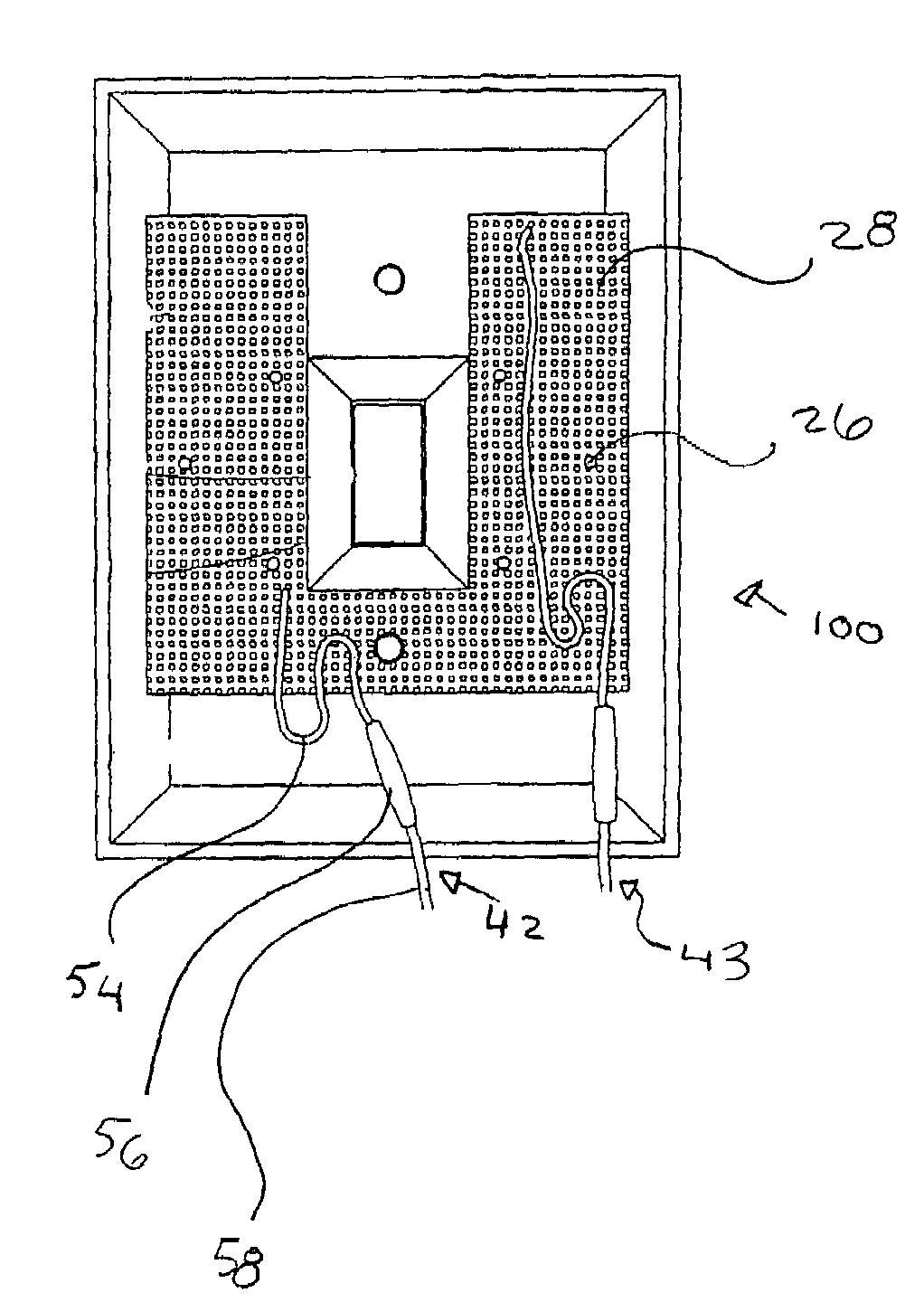
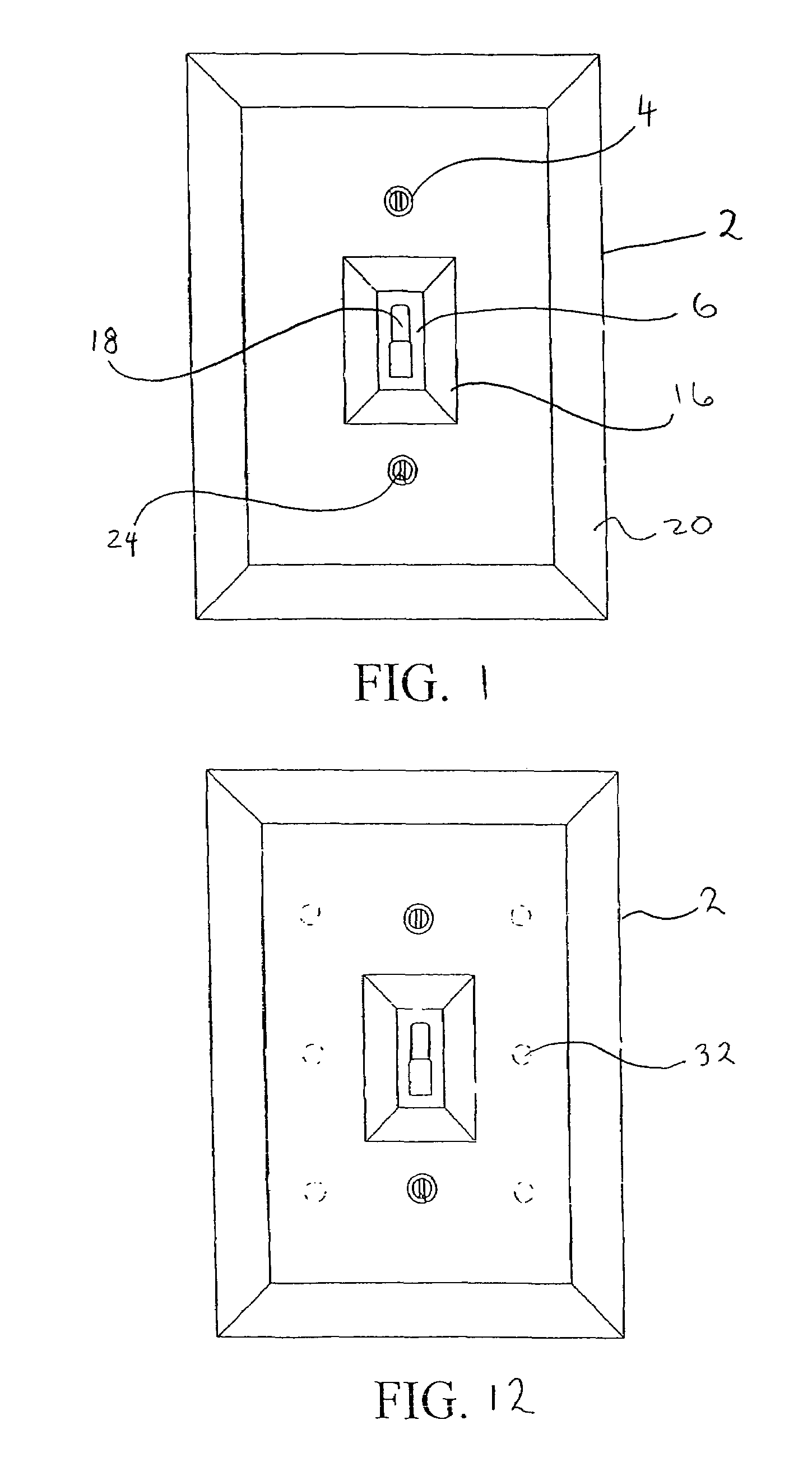
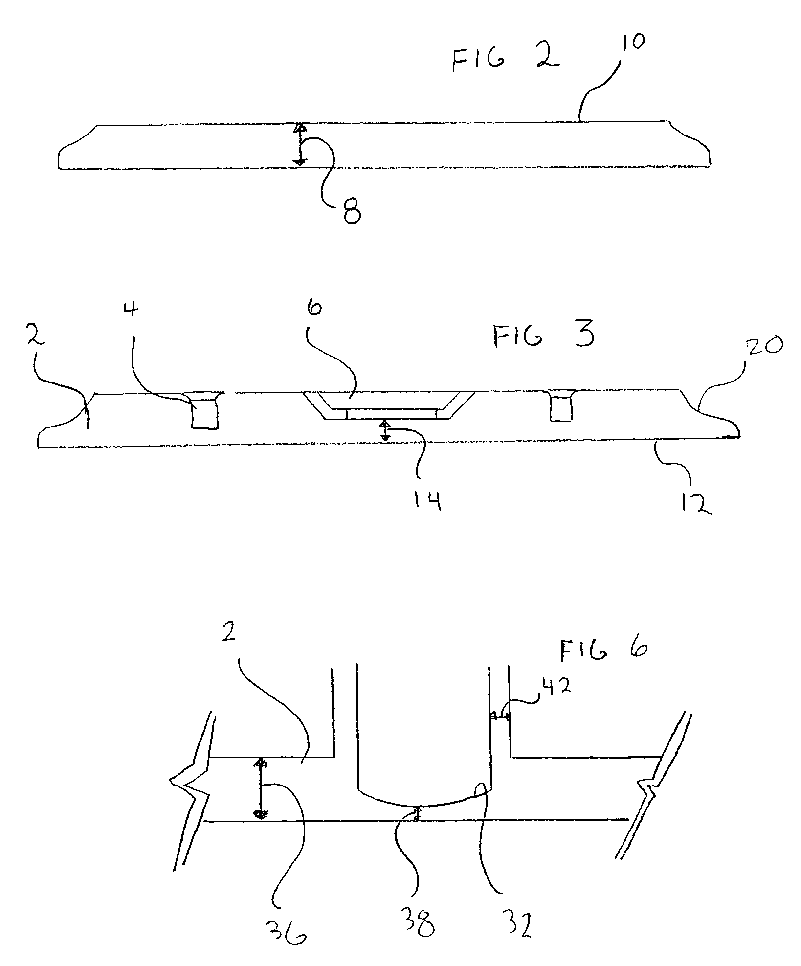
"The present invention provides an improved low level illumination system based on an LED electrical box cover plate that is able to preheat fluorescent lights if the electrical box controls one such light. The invention offers many advantages and innovative features, including low heat, low power consumption, and a broadly disbursed soft light capable of illuminating the general vicinity of the cover plate. Additionally, the invention is safe, shock resistant, and electro static discharge protected. The invention is ideal for night lighting in residential and commercial applications and offers a low level illumination system that overcomes the drawbacks of the prior art."

Problems solved by technology

The majority of residential, commercial and industrial buildings do not have an adequate low level illumination system to allow the safe and comfortable actions of people when the main light source is turned off.
While this may be partially overcome by the installation of portable night lights into an electrical outlet, therein lies one problem.
Since most night lights do not provide sufficient lighting in an area to adequately address the problem, it is common for people to leave on the bathroom light throughout the entire night.
There is a higher incidence of this by hotel patrons because of the unfamiliarity with the room.
As such hotels have unnecessarily high power consumption.
Other problems such as night light burnout, theft, breakage, heat, dimness and moderate power consumption are inherent with the use of conventional portable night lights.
A related problem is that most hotel rooms replace fluorescent lights at a higher than average rate.
This broad thermal change causes micro fractures in the end cap and at the glass / electrode interface.
This leads to the premature loss of gas from the light and early bulb failure.

Method used


Image

  • Illuminated electrical box cover plate
  • Illuminated electrical box cover plate
  • Illuminated electrical box cover plate

Examples


Embodiment Construction

[0031]There has thus been outlined, rather broadly, the more important features of the invention in order that the detailed description thereof that follows may be better understood and in order that the present contribution to the art may be better appreciated. There are, of course, additional features of the invention that will be described hereinafter and which will form the subject matter of the claims appended hereto.

[0032]In this respect, before explaining at least one embodiment of the invention in detail, it is to be understood that the invention is not limited in its application to the details of construction and to the arrangements of the components set forth in the following description or illustrated in the drawings. The invention is capable of other embodiments and of being practiced and carried out in various ways. Also, it is to be understood that the phraseology and terminology employed herein are for the purpose of descriptions and should not be regarded as limiting...


PUM


Abstract

The present invention is a low power and low heat dissipating, low illumination system that is based in an electrical box cover plate, preferably in a light switch cover plate. It allows for the maintenance of an electrical bleed current through the fluorescent light controlled by that light switch so as to keep a minimal thermal differential between the unlit and lit light. The light switch cover plate has a series of imbedded LEDs that illuminate an area all around the light switch. The unit is retrofittable on conventional light switches.

Description

[0001]This is a continuation in part of non provisional Utility patent application Ser. No. 11 / 497,773 filed Aug. 2, 2006 claiming priority from U.S. Provisional patent application Ser. No. 60 / 706,868 filed Aug. 10, 2005.BACKGROUND OF THE INVENTION[0002]The present invention relates to a low level illumination system, and, more particularly, to an illuminated cover plate for an electrical outlet or electrical switch. It is adapted to provide safety, energy savings and enhance florescent light longevity.[0003]The majority of residential, commercial and industrial buildings do not have an adequate low level illumination system to allow the safe and comfortable actions of people when the main light source is turned off. While this may be partially overcome by the installation of portable night lights into an electrical outlet, therein lies one problem. Illumination is needed at light switch and electrical controls, near doors and above counter tops. Many homes / hotels do not have night ...

Claims


Application Information

Patent Timeline
Patent Type & Authority Patents(United States)
IPC IPC(8): H01R33/00
CPCF21V33/006H01H9/182F21Y2101/02Y10S362/80F21Y2115/10
Inventor FAUNCE, MICHAEL JOSEPH
Owner FAUNCE MICHAEL JOSEPH
Learn More