Prosthetic device utilizing electric vacuum pump

a technology of electric vacuum pump and prosthetic device, which is applied in the field of prosthetic device utilizing electric vacuum pump, can solve the problems of inability to remove, heavy weight of weight activated pump, and difficulty in securing artificial limbs, etc., and achieves the effects of compact size, minimal power consumption, and convenient us

Active Publication Date: 2011-05-24
WILLOWWOOD GLOBAL LLC
View PDF24 Cites 46 Cited by
  • Summary
  • Abstract
  • Description
  • Claims
  • Application Information

AI Technical Summary

Benefits of technology

[0014]The present invention overcomes the disadvantages inherent to known prosthetic socket evacuation devices using mechanical (e.g., weight-activated) pumps. Rather, the present invention is directed to socket evacuation device employing an electrically-activated pump. Because the electrically-activated pump does not require manual manipulation to create vacuum, it is substantially easier to use than a manual pump. Further, due to the compact size and minimal power consumption associated with an evacuation device of the present invention, it may be readily incorporated into / onto a prosthesis.

Problems solved by technology

Artificial limbs have been in use throughout history, having been first recorded circa 2750 B.C. During that period of time, interfacing and suspending an artificial limb has been a continuing challenge.
Creating a reliable sub atmospheric pressure chamber between the residual limb and prosthetic device has, however, proved to be a challenge.
First, the weight activated pump is heavy, and cannot be removed even in the case of a pump failure.
This prohibits the use of this technology for many artificial limb users.
Further, a weight-activated pump system requires some number of weight activated strokes before becoming effective.
The hand-held pump is also awkward for many individuals to use and requires a certain amount of dexterity and strength to operate.
This is a common problem for elderly individuals.
Aside from those specific disadvantages detailed above, such mechanical systems are further burdened with other general problems.
Therefore, one general disadvantage to such a mechanical systems is that the pump is unable to draw vacuum when the user is sedentary.
This means that absent the carrying and use of a separate hand-held pump, there is no way to properly don an associated prosthesis without standing up and walking on the prosthesis in a partially donned (i.e., non-evacuated) state.
Similarly, if the socket loses pressure while the user is sitting or otherwise non-ambulatory, there is no way (aside from a separate hand-held pump) to re-evacuate the socket other than walking or bouncing on the now improperly suspended prosthesis.
Yet another disadvantage to such mechanical evacuation systems is that a weight-activated pump will always eventually evacuate the prosthetic socket to some predetermined level.
As such, there is no way for a user to adjust the level of vacuum to coincide with a particular activity or comfort level.
For example, a user would not be able to increase the vacuum level over some typical vacuum level during a period of increased activity, nor decrease the vacuum level to compensate for a particularly sore or sensitive residual limb.

Method used


Image

  • Prosthetic device utilizing electric vacuum pump
  • Prosthetic device utilizing electric vacuum pump
  • Prosthetic device utilizing electric vacuum pump

Examples


Embodiment Construction

)

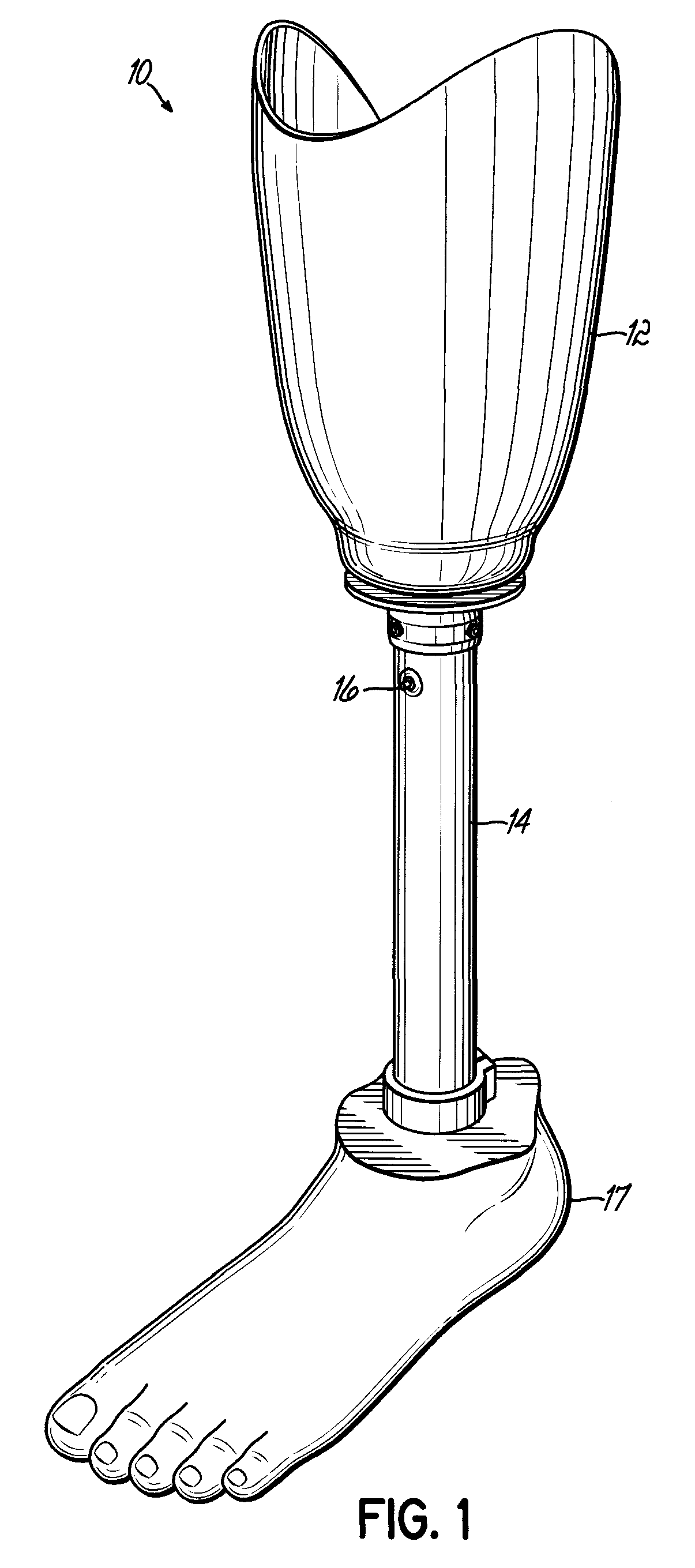
[0041]FIG. 1 illustrates one embodiment of a prosthesis 10 in accordance with principles of the present invention. The prosthesis includes a socket 12 for receiving an amputee's residual limb, a column (pylon) 14, which is typically a cylindrical section of lightweight metal such as aluminum, and an artificial foot 17. As can be seen in FIG. 1, the pylon 14 includes a vacuum actuator button 16 used to actuate an electric vacuum pump within the pylon that draws air from the socket 12 and, as a result, draws the residual limb into intimate contact with the interior of the socket 12.

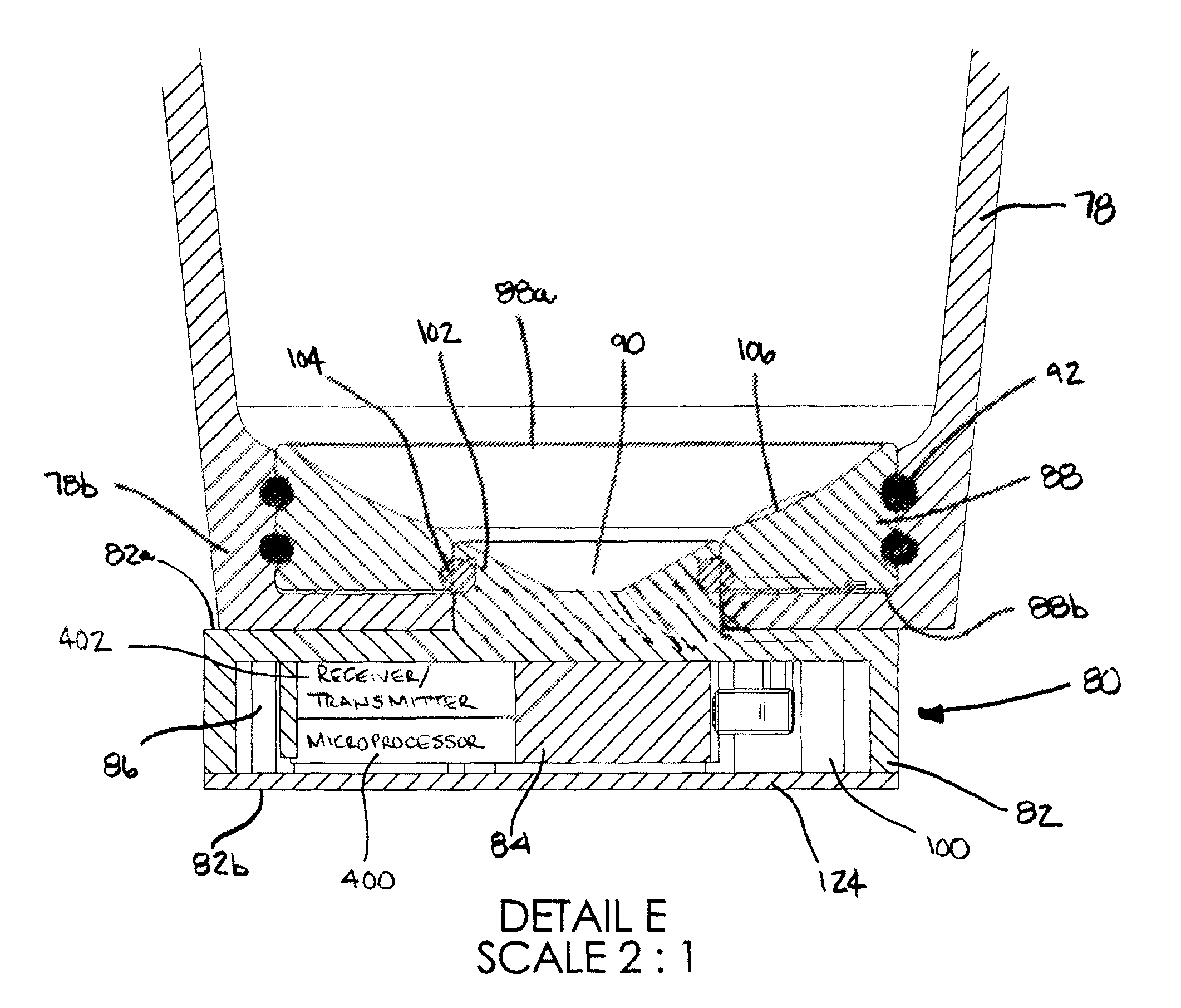
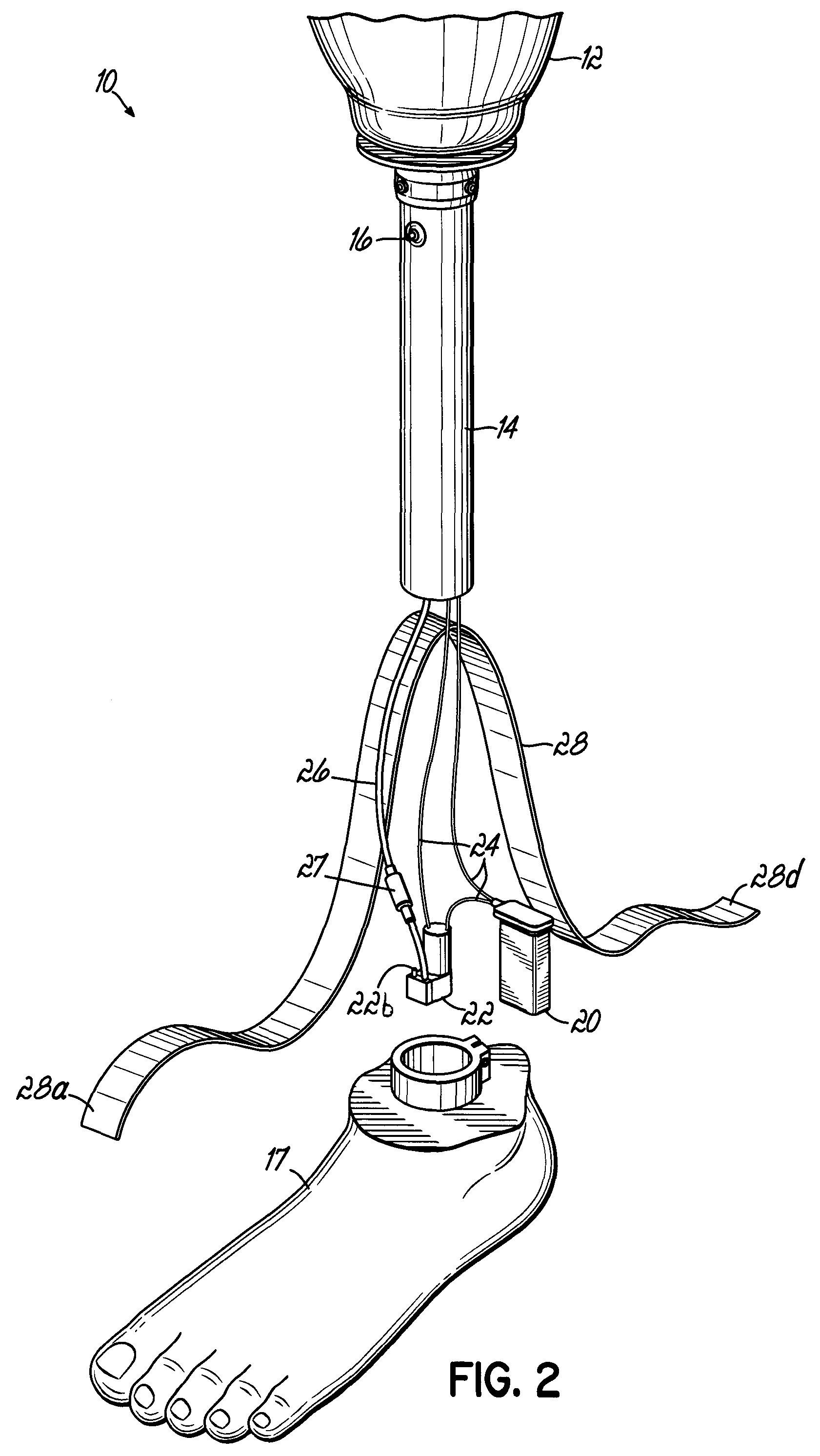
[0042]FIG. 2 illustrates the prosthesis of FIG. 1 in a disassembled state to show the component parts within the pylon 14. Internal to the pylon 14 is a power source 20, such as a capacitor or a conventional 9-volt battery, a vacuum pump 22, and electrical lines 24 for delivering electrical power from power source 20 to vacuum pump 22, and vacuum line 26 for drawing vacuum from socket 12 through a check va...


PUM


Abstract

Evacuation devices for evacuating the socket of a prosthetic limb, and prosthetic limb systems employing such vacuum devices. The evacuation devices each preferably include at least an electrically powered vacuum pump and a power source. Such evacuation devices can be attached at various locations on or in a prosthetic limb. Because the electrically powered pump does not require manual manipulation to create vacuum, it is substantially easier to use than a manual pump. Due to the small size and small power source required by such an electrically powered pump, an evacuation device may be readily incorporated into a prosthesis.

Description

[0001]The present application is a continuation-in-part of U.S. patent application Ser. No. 11 / 149,858, filed on Jun. 10, 2005.BACKGROUND OF THE INVENTION[0002]The present invention is directed to electrically-powered evacuation devices for use in evacuating a prosthetic socket and / or to prosthetic limbs incorporating such electrically-powered evacuation devices. The present invention is also directed to various systems and methods for monitoring, performing, and controlling such devices.[0003]Artificial limbs have been in use throughout history, having been first recorded circa 2750 B.C. During that period of time, interfacing and suspending an artificial limb has been a continuing challenge. Various and numerous theories and anatomical constructs have been used over time in an evolving manner, and these have revealed a number of key factors in maximizing comfort and functional potential for persons who wear artificial limbs.[0004]Firstly, the surgical procedure used to perform lim...

Claims


Application Information

Patent Timeline
Patent Type & Authority Patents(United States)
IPC IPC(8): A61F2/48A61F2/80A61F2/60A61F2/78
CPCA61F2/68A61F2/80A61F2/5044A61F2220/0041A61F2/60A61F2/76A61F2002/30359A61F2002/30433A61F2002/5032A61F2002/607A61F2002/6614A61F2002/701A61F2002/704A61F2002/705A61F2002/742A61F2002/747A61F2002/748A61F2002/7635A61F2002/764A61F2002/802A61F2002/805A61F2220/0033A61F2/54A61F2/70A61F2/74A61F2/742A61F2/748
Inventor HAINES, WILBUR A.COLVIN, JAMES M.HAYNES, MICHAEL L.KELLEY, CHRISTOPHER T.FORD, MARK W.GROVES, MARK W.DENUNE, JEFFREY A.
Owner WILLOWWOOD GLOBAL LLC
Why Eureka
Try Eureka