Connector for a respiratory mask and a respiratory mask

a technology of connecting rods and respiratory masks, which is applied in the direction of breathing masks, breathing protection, other medical devices, etc., can solve the problems of increasing noise, unpleasant whistling effect, and exhausting exhaled gas to the atmosphere through gas washout vents, so as to reduce turbulence, reduce pressure gradient, and smooth cross-section

Inactive Publication Date: 2006-07-06
RESMED LTD
View PDF24 Cites 39 Cited by
  • Summary
  • Abstract
  • Description
  • Claims
  • Application Information

AI Technical Summary

Benefits of technology

[0028] The vent passage desirably comprises an inlet portion of constant cross-section, a relatively long outlet portion of constant cross-section and a relatively short transition portion of smoothly reducing cross-section extending from the inlet portion to the outlet portion. This shape reduces turbulence and affords a pressure drop from the interior of the mask to the outlet of the vent passage which reduces the pressure gradient at the outlet of the vent passage and, thus, reduces the noise generated.

Problems solved by technology

The exhausting of exhaled gas to the atmosphere through the gas washout vent creates noise due to turbulence generated at a shear layer between the moving vented gases and the still atmospheric air.
The decreased area regions increase by the velocity of the gas flowing therethrough which increases noise and can produce an unpleasant whistling effect.
Secondly, the flow of the gas from the vent outlet to a state where its velocity is in substantial equilbrium with the atmosphere is interrupted by an external shoulder closely downstream of the vent outlet.
The stresses in the flow caused by the shoulder lead to the generation of noise.
Additionally, the flow path from the gas conduit into the vent outlet is not smooth which introduces discontinuities into the flow which result in further noise generation.
This reduces CO2 washout efficiency, as noted above, and requires additional patient effort to force the gas against the direction of flow coming from the flow generator.

Method used


Image

  • Connector for a respiratory mask and a respiratory mask
  • Connector for a respiratory mask and a respiratory mask
  • Connector for a respiratory mask and a respiratory mask

Examples


Embodiment Construction

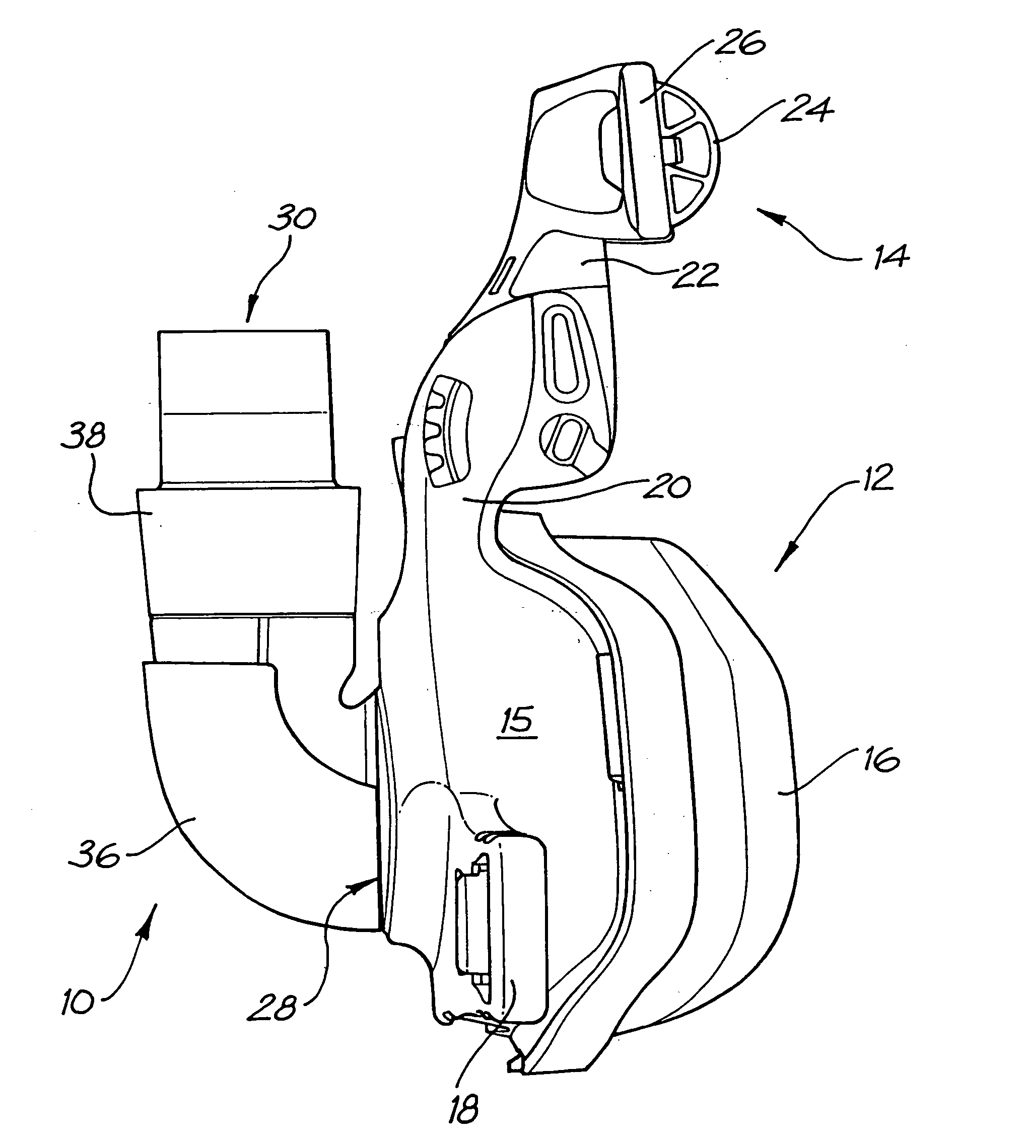
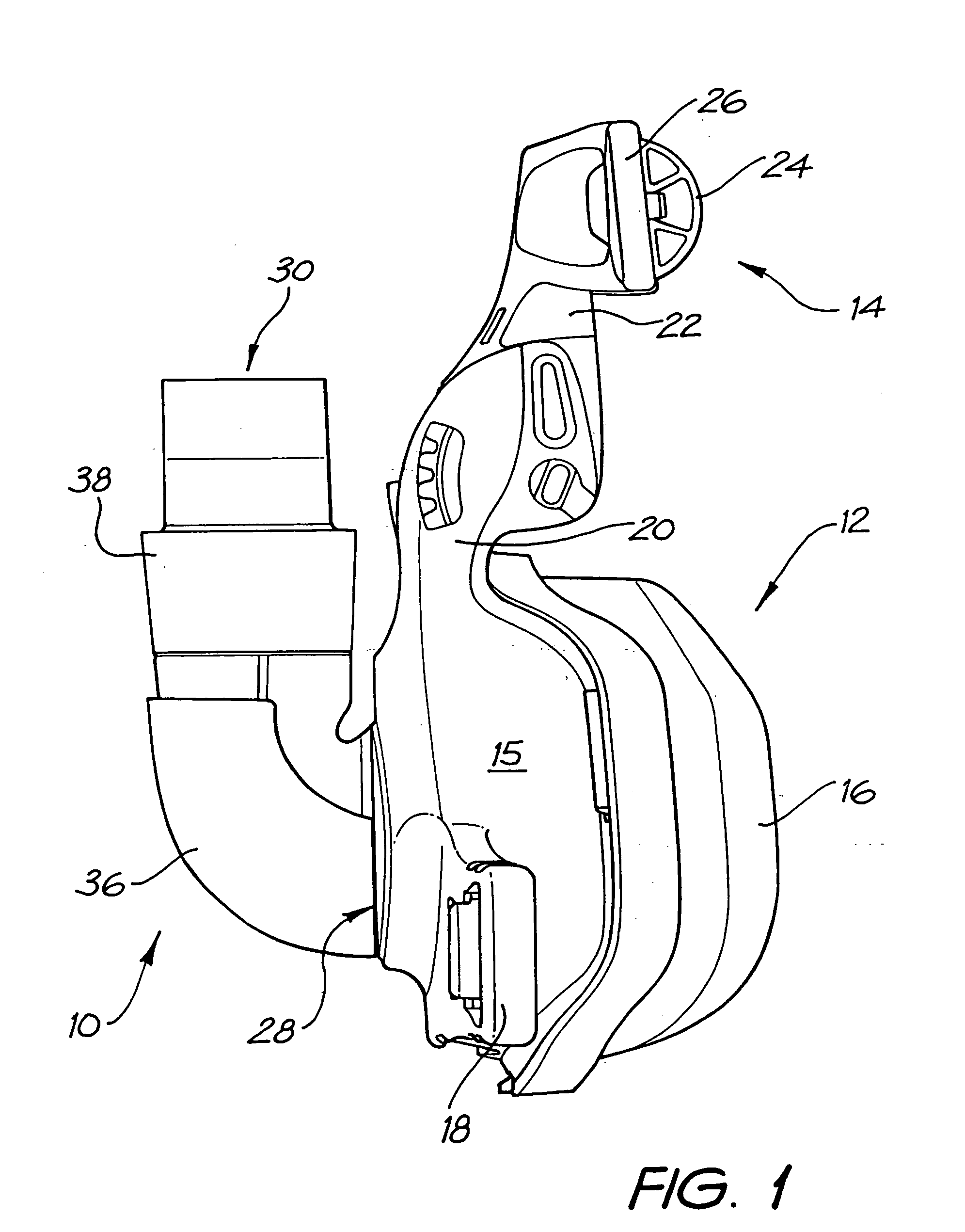
[0053] FIGS. 1 to 5 show a first embodiment of the first aspect of the invention in the form of connector 10. The connector 10 is shown attached to a nasal respiratory mask 12 and forehead support device 14. The connector 10 is also suitable for use with a full face (i.e., nose and mouth) respiratory mask.

[0054] The mask 12 comprises a substantially rigid mask shell 15, a flexible mask cushion 16 and two slotted lower head strap connectors 18 (only one connector shown).

[0055] The forehead support device 14 includes a lower portion 20 which is pivotally mounted to an upper portion 22. The upper portion 22 includes forehead cushions 24 and two slotted upper head strap connectors 26 (only one cushion / connector shown).

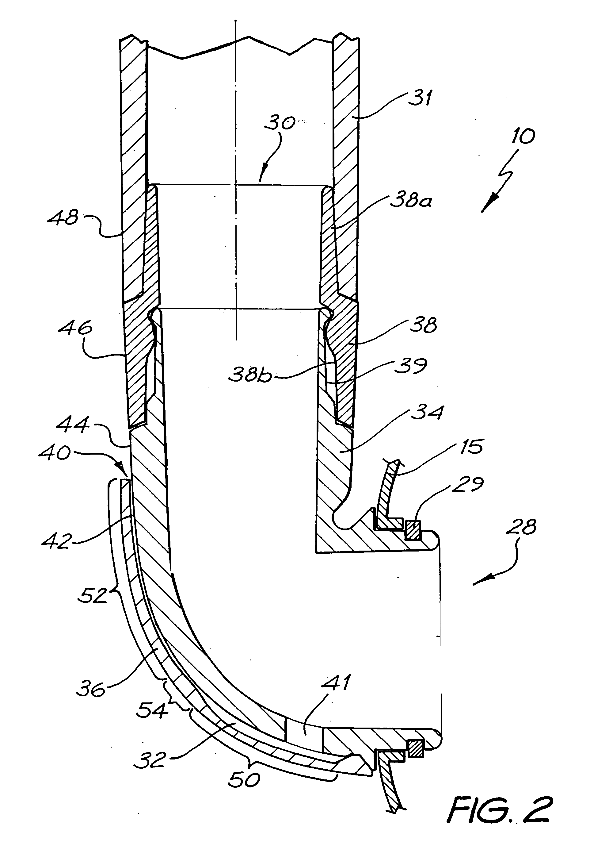
[0056] As best shown in FIG. 2, the connector 10 includes a mask end 28 for connecting in fluid communication with the interior of the respiratory mask 12 and a supply conduit end 30 disposed substantially perpendicularly to the mask end 28 for connecting in fluid commu...


PUM


Abstract

A connector includes a mask end for connecting with the interior of a respiratory mask, a supply conduit end, and a gas washout vent passage having an inlet adjacent to, or forming part of, the mask end in fluid communication with the interior of the respiratory mask and an outlet in fluid communication with atmosphere. The vent outlet of the vent passage is disposed on the side of the connector remote from the mask end. A respiratory mask includes a mask shell, a mask inlet for connecting with the outlet of a breathable gas supply conduit, and a gas washout vent passage. A vent outlet is disposed on the side of the mask remote from the mask interior and is adapted to direct the washout gas in a direction substantially parallel to the longitudinal axis of the mask inlet and away from the mask inlet.

Description

BACKGROUND OF THE INVENTION [0001] 1. Field of Invention [0002] The present invention relates to a connector for a respiratory mask and a respiratory mask. [0003] The invention has been developed primarily for use with a breathable gas supply apparatus in Continuous Positive Airway Pressure (CPAP) treatment of, for example, Obstructive Sleep Apnea (OSA) and other ventilatory assistance treatments, such as Non Invasive Positive Pressure Ventilation (NIPPV) and will be described hereinafter with reference to these applications. However, it will be appreciated that the invention is not limited to these particular fields of use and also finds application in, for example, assisted respiration, mechanical ventilation and the like. [0004] 2. General Background and Related Art [0005] CPAP treatment is a common ameliorative treatment for breathing disorders including OSA. CPAP treatment, as described in U.S. Pat. No. 4,944,310, provides pressurized air or other breathable gas to the entrance...

Claims


Application Information

Patent Timeline
Patent Type & Authority Applications(United States)
IPC IPC(8): A62B18/02A61M16/06A61M16/08
CPCA61M16/06A61M16/08A61M16/0816A61M2205/42A61M2206/14A61M16/0066A61M16/0683A61M16/0875A61M16/0616A61M16/0622A61M16/0633A61M16/0638A61M2202/0225A61M16/0825A61M2202/0085A61M16/0666
Inventor GUNARATNAM, MICHAEL K.DREW, JOANNE E.CRUMBLIN, GEOFFREYJENKINSON, PHILLIPLYNCH, SUSAN R.
Owner RESMED LTD
Why Eureka
Try Eureka