Tool cabinet

Inactive Publication Date: 2006-07-06
SUPER TEST CORP
View PDF18 Cites 18 Cited by
  • Summary
  • Abstract
  • Description
  • Claims
  • Application Information

AI Technical Summary

Benefits of technology

[0004] Therefore, it is a primary objective of the present invention to install a protective sleeve onto an installing hole of a frame as to protect the exterior of the frame and prevent the exterior of the frame from being damaged when the hand tools are inserted into the installing holes and the tool cabinet is moved.
[0005] The tool cabinet in accordance with the present invention comprises a frame, a carrying surface being disposed on the frame, at least one installing hole being disposed on the carrying surface, and a bar-shape protective sleeve being engaged into the installing hole, wherein the protective sleeve has an accommodating space being interconnected to the installing hole and provided for storing a hand tool, such that the protective sleeve is capable to accommodate the insertion of a hand tool and allow the hand tool to be isolated by the protective sleeve and inserted into the installing hole. Therefore, when a user pushes the tool cabinet, it reduces the shaking of the hand tools and prevents a direct collision of the rear end of a hand tool on the frame as to assure the protection of the exterior of the frame from being damaged by the collisions of the hand tools and effectively maintains the good look of the frame.

Problems solved by technology

Therefore, when these long bar-shape hand tools are inserted into the installing holes, the hand tools will go all the way to the bottom of the frame, which will cause damages to the exterior of the frame when the frame is moved or the hand tools are shaken severely.

Method used


Image

  • Tool cabinet
  • Tool cabinet
  • Tool cabinet

Examples


Embodiment Construction

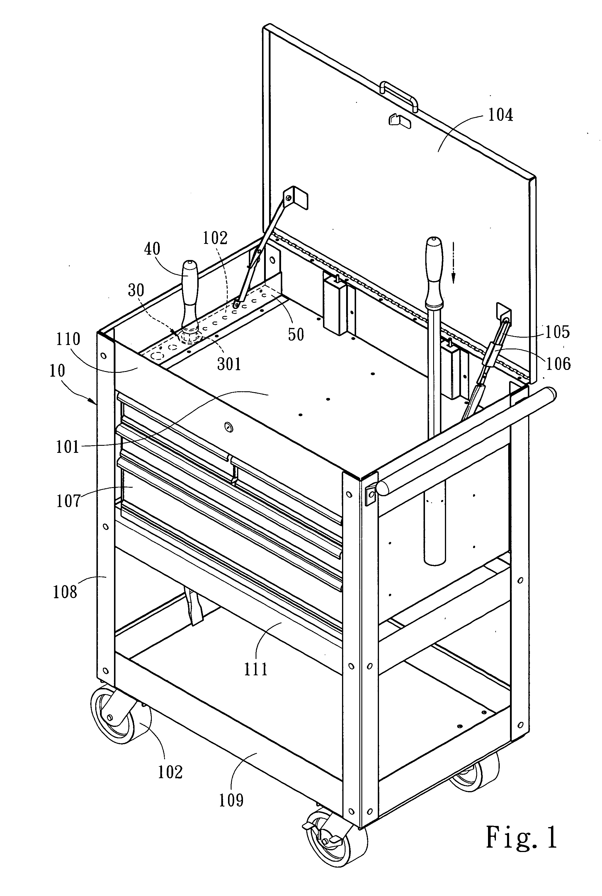
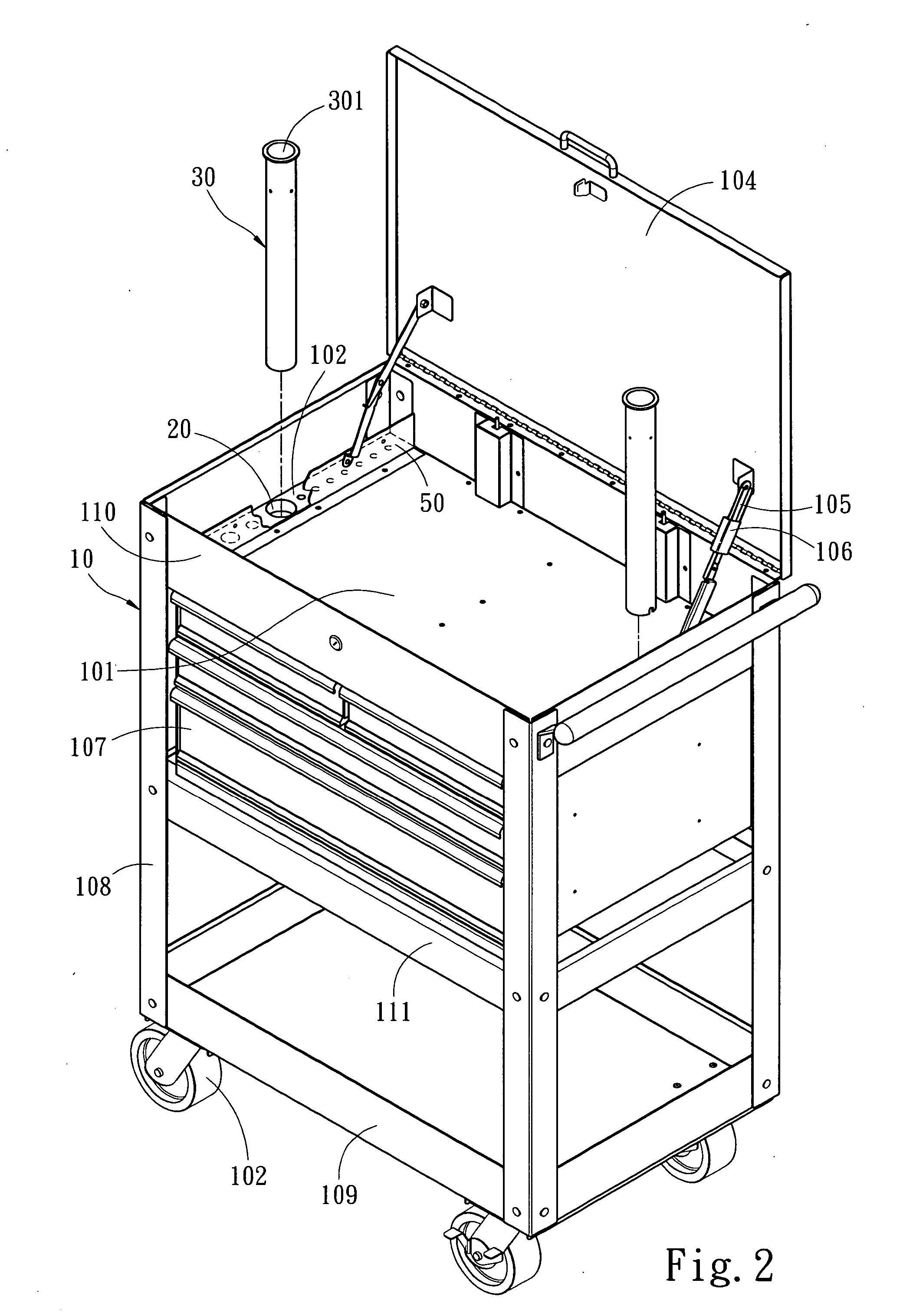
[0011] To make it easier for our examiner to understand the objects, features, and advantages of the present invention, the detailed description accompanied with drawings of a preferred embodiment are provided as follows.

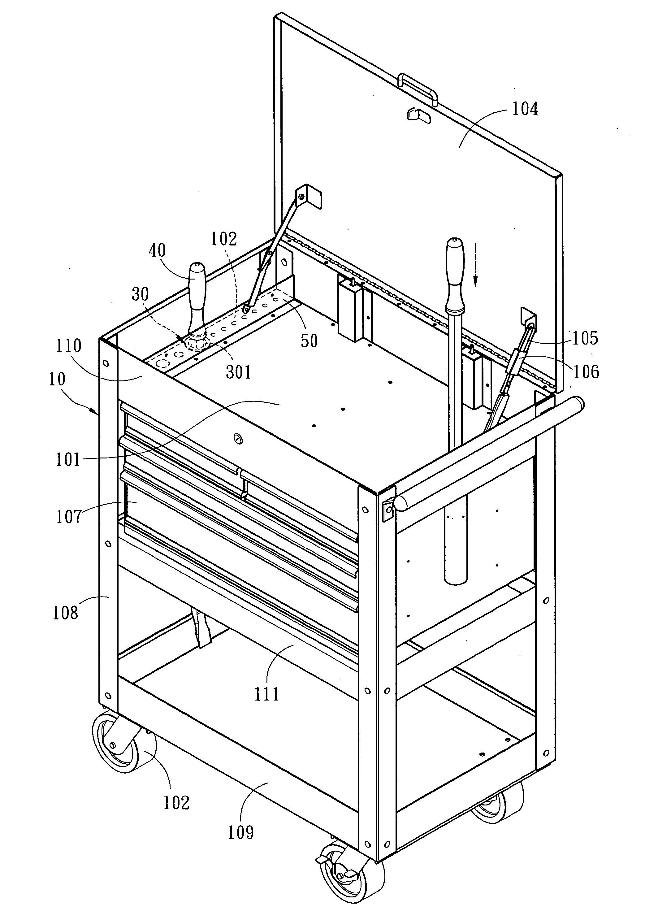
[0012] Please refer to FIGS. 1 and 2 for a tool cabinet in accordance with the present invention. The tool cabinet comprises a frame 10, and the frame 10 is made of four corner pillars 108 and at least one shelf 111 installed between the corner pillars 108. The shelf 111 includes an upper shelf 110 and a lower shelf 109, and the frame has at least one drawer 107 disposed therein for carrying objects, so that a user can store desired objects. The upper shelf 110 of the frame 10 has a carrying surface 101, and the lower shelf 109 has a movable wheel set 102. The carrying surface 101 has at least one installing hole 20 for accommodating a bar-shape hand tool 40. The installing hole 20 is usually built on both sides of the carrying surface 101, and a bar-shape protecti...


PUM


Abstract

The present invention discloses a tool cabinet that can be pushed by users to a working site for maintenance or an assembling operation, and the carrying surface of a frame of the tool cabinet has at least one installing hole engaged by a protective sleeve, so that a long bar-shape hand tool can be isolated by the protective sleeve and inserted into the installing hole to protect the frame from being collided directly by the hand tool and prevent damages of the external look of the frame.

Description

FIELD OF THE INVENTION [0001] The present invention relates to a tool cabinet, more particularly to a tool cabinet capable of protecting the exterior of the tool cabinet from being damaged. BACKGROUND OF THE INVENTION [0002] There are various different kinds of traditional tool cabinets, including those disclosed in the R.O.C. Patent Publication No. 435321 and the U.S. Pat. Nos. 6,742,854, 6,572,203 and 6,347,848. The tool cabinet carries various kinds of hand tools and has wheels installed at its bottom, so that a user can push the tool cabinet to a working site for maintenance or an assembling operation. A partition board is used to define a storage area on the carrying surface of a frame of a traditional tool cabinet, and the storage area has a plurality of installing holes, and these installing holes are provided for inserting bar-shape hand tools as to constitute an easy-to-use, and convenient-to-arrange tool cabinet. [0003] Although the aforementioned traditional tool cabinets...

Claims


Application Information

Patent Timeline
IPC IPC(8): A47B46/00
CPCB25H3/00
Inventor HUNG, SUE-TSEN
Owner SUPER TEST CORP
Why Eureka
Try Eureka