
Beating and rubbing device

A technology of vertical movement and substrate, applied in kneading massage equipment, physical therapy, vibration massage and other directions, it can solve the problems of large overhang distance, inaccurate sliding relationship and power consumption.

Active Publication Date: 2017-05-10
杨宗勋
View PDF6 Cites 0 Cited by
  • Summary
  • Abstract
  • Description
  • Claims
  • Application Information

AI Technical Summary

Problems solved by technology

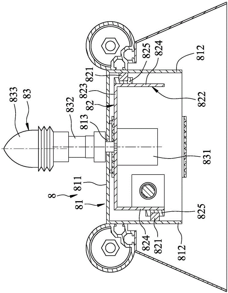
[0003] The disadvantage of the aforementioned patents is that since the kneading motor 831 of the kneading unit 83 is arranged on the abutment plate 823 of the vertical movement bearing 822, and the power shaft 832 needs to pass through the long slot 813, the kneading head The power shaft 832 between the component 833 and the kneading motor 831 has a large hanging distance, which not only consumes more power during operation, but also produces a large shaking, which cannot improve the comfort
[0004] Furthermore, another shortcoming of the above-mentioned patent is that the longitudinal movement seat 822 is a "ㄇ" shape in which the metal plate is concavely folded into a right angle, and the longitudinal movement seat 822 will have elastic recovery force due to the material itself, and also That is, the support plate 824 has a tendency to return to be parallel to the abutment plate 823. When the support plate 824 of the longitudinal movement bearing 822 elastically recovers, the sliding seat 825 and the longitudinal movement guide rail The sliding relationship between 821 will no longer be accurate, and the sliding seat 825 will produce offset friction with the longitudinal guide rail 821 due to the deformation of the support plate 824

Method used


Image

  • Beating and rubbing device
  • Beating and rubbing device
  • Beating and rubbing device

Examples


Embodiment Construction

[0021] The present invention will be described in detail below in conjunction with the accompanying drawings and embodiments.

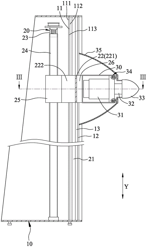
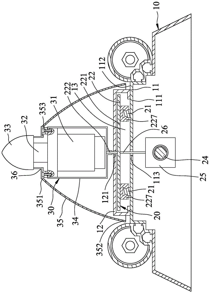
[0022] refer to figure 2 and image 3 , the first embodiment of the kneading device of the present invention includes a base frame 10 , a longitudinal movement unit 20 and a kneading unit 30 .

[0023] The pedestal 10 can be stably erected on the ground, and has a base plate 11 extending along a vertical axis Y, a protective cover 12 fixed on the base plate 11 and a gap formed between the base 11 and the protective cover 12 The base plate 11 has an inner surface 111, an outer surface 112 opposite to the inner surface 111, and a long groove 113 passing through the inner surface 111 and the outer surface 112 and extending along the vertical axis Y, The protection cover 12 is fixed on the outer surface 112 and has a guide groove 121 corresponding to the long groove 113 .

[0024] The longitudinal movement unit 20 has two longitudinal movement guide r...


PUM


Abstract

A beating and rubbing device comprises a base frame, a longitudinal moving unit and a beating and rubbing unit. The longitudinal unit is provided with two longitudinal moving guide rails installed on the base frame, a longitudinal moving supporting base and a longitudinal moving driving element, the beating and rubbing unit is connected with the longitudinal moving supporting base, located outside one outer side face of a base plate of the base frame and provided with a beating and rubbing motor, a power shaft and a beating and rubbing head element installed on the power shaft, and the power shaft can drive the beating and rubbing head element to rotate. The beating and rubbing unit is located outside the base plate of the base frame and can reduce the overhanging length of the power shaft so as to improve the operation stability of the beating and rubbing device.

Description

technical field [0001] The invention relates to a massage device, in particular to a kneading device. Background technique [0002] refer to figure 1 , a kind of kneading device 8 in the past, disclosed as China Taiwan Patent Certificate No. M450373, this kneading device 8 comprises a base frame 81, a vertical movement unit 82 and a kneading unit 83, and this base frame 81 has an upright base plate 811, two side plates 812 vertically connected to the base plate 811, and a long slot 813 passing through the base plate 811; A longitudinal movement bearing 822 arranged on the longitudinal movement guide rail 821, and a longitudinal movement driving member (not shown) that drives the longitudinal movement bearing 822 to vertically move up and down along the longitudinal movement guide rail 821, the longitudinal movement bearing 822 There is a support plate 823 parallel to the base plate 811, two support plates 824 vertically connected to the support plate 823, and two sliding s...

Claims


Application Information

Patent Timeline
Patent Type & Authority Applications(China)
IPC IPC(8): A61H7/00A61H23/02
CPCA61H7/007A61H23/006A61H23/02A61H2023/002A61H2201/01A61H2201/0165A61H2201/0169A61H2201/1207
Inventor 杨宗勋
Owner 杨宗勋
Learn More