Single-layer multiple-span bent column crane beam positioning method

A technology of multi-span bent frame and positioning method, which is applied in the field of positioning and configuration of crane girders, can solve problems such as unsatisfactory use effects, cross-sectional dimensions of side columns and central columns, differences in foundation size and reinforcement area, and inconsistent eccentricity, etc., to achieve The effect of reasonable reinforcement, shortened overhang length, and uniform force

Inactive Publication Date: 2009-12-16
GUIYANG AL-MG DESIGN & RES INST
View PDF2 Cites 1 Cited by
  • Summary
  • Abstract
  • Description
  • Claims
  • Application Information

AI Technical Summary

Problems solved by technology

For a factory building with single-story multi-span bent columns, if it is configured according to the standards in the prior art, the distance from the center line of the crane beam installed on the corbels of the bent side columns to the span marking line of the bent side columns The distance is equal to the distance from the center line of the crane girder installed on the corbel of the center column of the bent frame to the span marking line of the center column of the bent frame. The positioning configuration method with equal marking distances will cause inconsistencies in the eccentricity of the crane load to the side columns and the middle columns of the bent frame in actual use, resulting in differences in the cross-sectional dimensions, foundation sizes and reinforcement areas of the side columns and the middle columns. This difference is more prominent when the tonnage of the crane is larger
Therefore when this crane girder positioning method in the prior art is in use, its use effect is still not ideal enough

Method used


Image

  • Single-layer multiple-span bent column crane beam positioning method

Examples


Embodiment Construction

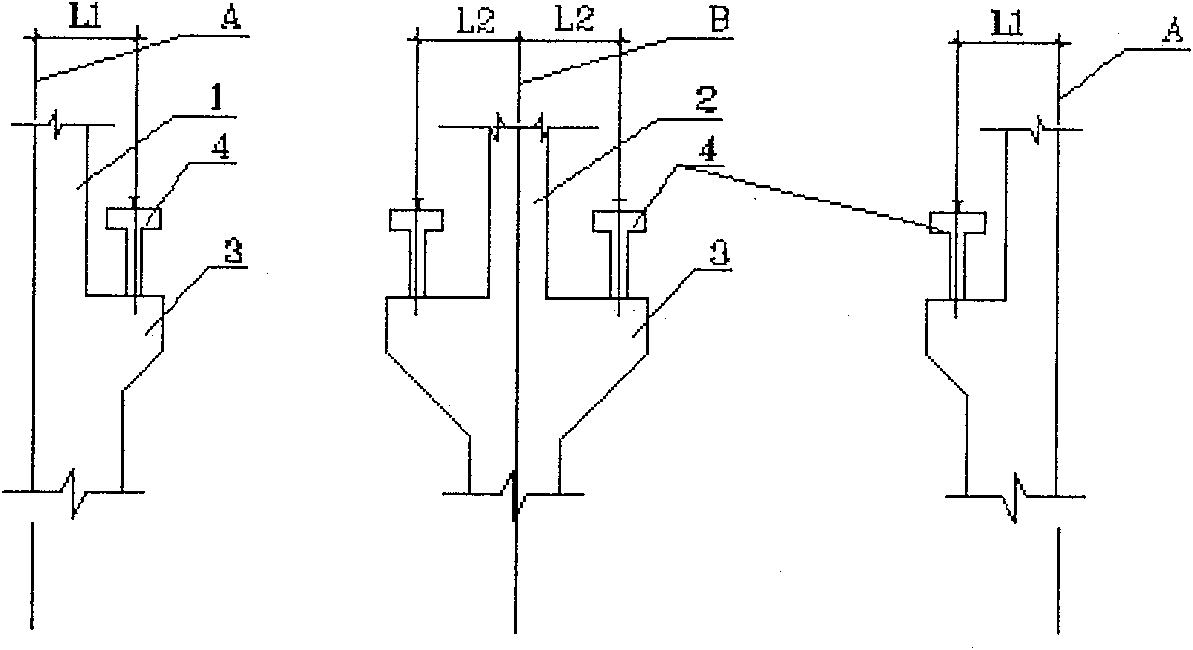
[0010] Implementation example of the present invention: when the crane beam 4 is installed on the bracket 3 of the side column 1 of the single-layer multi-span bent column and the corbel 3 of the middle column 2 of the bent frame, the corbel 1 installed on the side column 1 of the bent frame The distance from the center line of the crane beam 4 on 3 to the span marking line A of the side column 1 of the bent frame is L1, so that the center line of the crane beam 4 installed on the corbel 3 of the middle column 2 of the bent frame is connected to the middle column of the bent frame The distance between the span marking line B of 2 is L2, and L1 is greater than L2; the length of L1 and L2 can be determined according to the specific construction situation. Generally, the length of L1 is longer than the length of L2. The range is controlled within 50-500 mm The range may be controlled within the range of 100-300 mm; for the convenience of construction, it is best to set the length ...


PUM


Abstract

The invention discloses a positioning method for a crane beam of a single-layer multi-span bent column. The distance from the center line of the crane beam installed on the corbel of the side column of the bent frame to the span marking line of the side column of the bent frame is L1, so that the center line of the crane beam installed on the corbel of the middle column of the bent frame to the span line of the bent frame The distance between the span markings of the center column is L2, and L1 is greater than L2. The invention adjusts the positioning dimension between the center line of the crane beam on the corbel of the traditional bent frame side column and the center column and the span marking line of the column, so that the effect of a single crane load on the side column and the center column is basically the same. The invention has the advantages of making the single-layer multi-span bent frame column and the foundation evenly stressed, and has the advantages of saving engineering investment and the like.

Description

Technical field: [0001] The invention relates to a positioning and configuration method for a crane beam, in particular to a positioning method for a single-layer multi-span bent column crane beam. technical background: [0002] At present, standard single-story industrial plants that meet the building modulus generally have standard lifting equipment, that is, single-girder cranes or double-girder bridge cranes. Industrial plants with different standard spans are equipped with cranes with corresponding spans. For a factory building with single-story multi-span bent columns, if it is configured according to the standards in the prior art, the distance from the center line of the crane beam installed on the corbels of the bent side columns to the span marking line of the bent side columns The distance is equal to the distance from the center line of the crane girder installed on the corbel of the center column of the bent frame to the span marking line of the center column o...

Claims


Application Information

Patent Timeline
Patent Type & Authority Patents(China)
IPC IPC(8): B66C7/00
Inventor 赵仁芳
Owner GUIYANG AL-MG DESIGN & RES INST
Why Eureka
Try Eureka