RFID devices for enabling reading of non-line-of-sight items

a technology of rfid tags and items, applied in the direction of burglar alarm mechanical actuation, instruments, transportation and packaging, etc., can solve the problems of impaired effective reading of tags located in the center of stacks, difficult to read stacks of items with rfid tags, and difficult to track metal products or those with high water content, etc., to achieve effective reading effect of the reader

Active Publication Date: 2006-07-06
AVERY DENNISON CORP
View PDF7 Cites 39 Cited by
  • Summary
  • Abstract
  • Description
  • Claims
  • Application Information

AI Technical Summary

Benefits of technology

[0011] In accordance with exemplary embodiments of the present invention, radio-frequency identification (RFID) apparatus and methodology are provided that enable the RFID tags in a stack of RFID-tagged items, such as shipping and storage containers, cartons, and boxes, including items that are RF obscured or do not have a direct line of sight to an RFID reader, to be read effectively by the reader.

Problems solved by technology

One of the inherent difficulties in this application is ensuring that all of the RFID tags associated with all of the items in the stack are read, including the inner items of the stack that are obscured from view by the outer items of the stack.
The effectiveness of reading tags located in the center of a stack may be impaired by the presence of materials that are not particularly conducive to RF reading.
These characteristics make tracking metal products or those with high water content problematic.
In addition, reading a stack of items with RFID tags, particularly items located in the center of the stack or items that may contain highly conductive or absorptive materials, is also problematic.

Method used


Image

  • RFID devices for enabling reading of non-line-of-sight items
  • RFID devices for enabling reading of non-line-of-sight items
  • RFID devices for enabling reading of non-line-of-sight items

Examples


Embodiment Construction

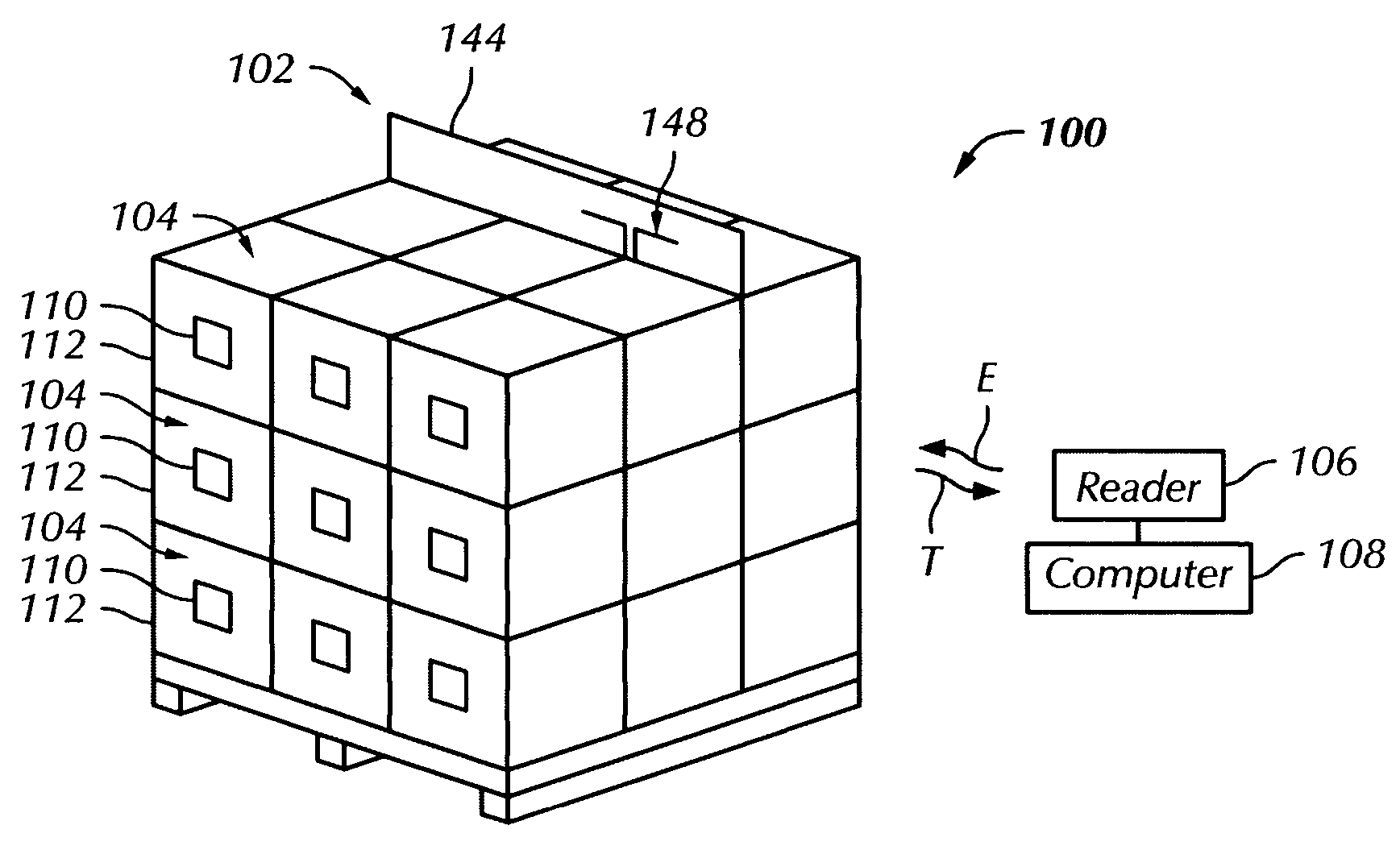
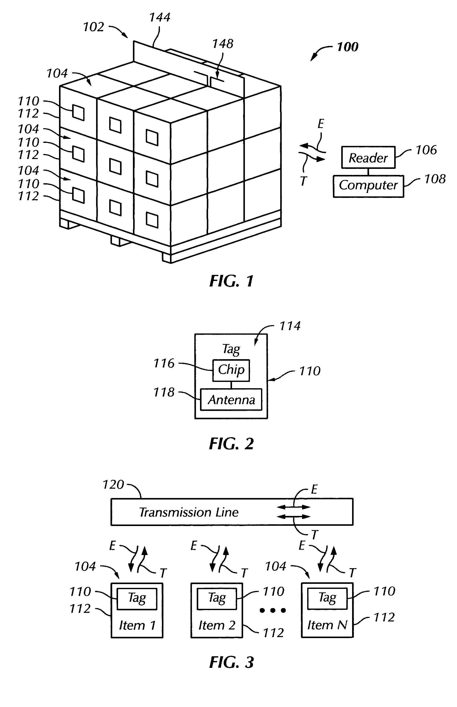
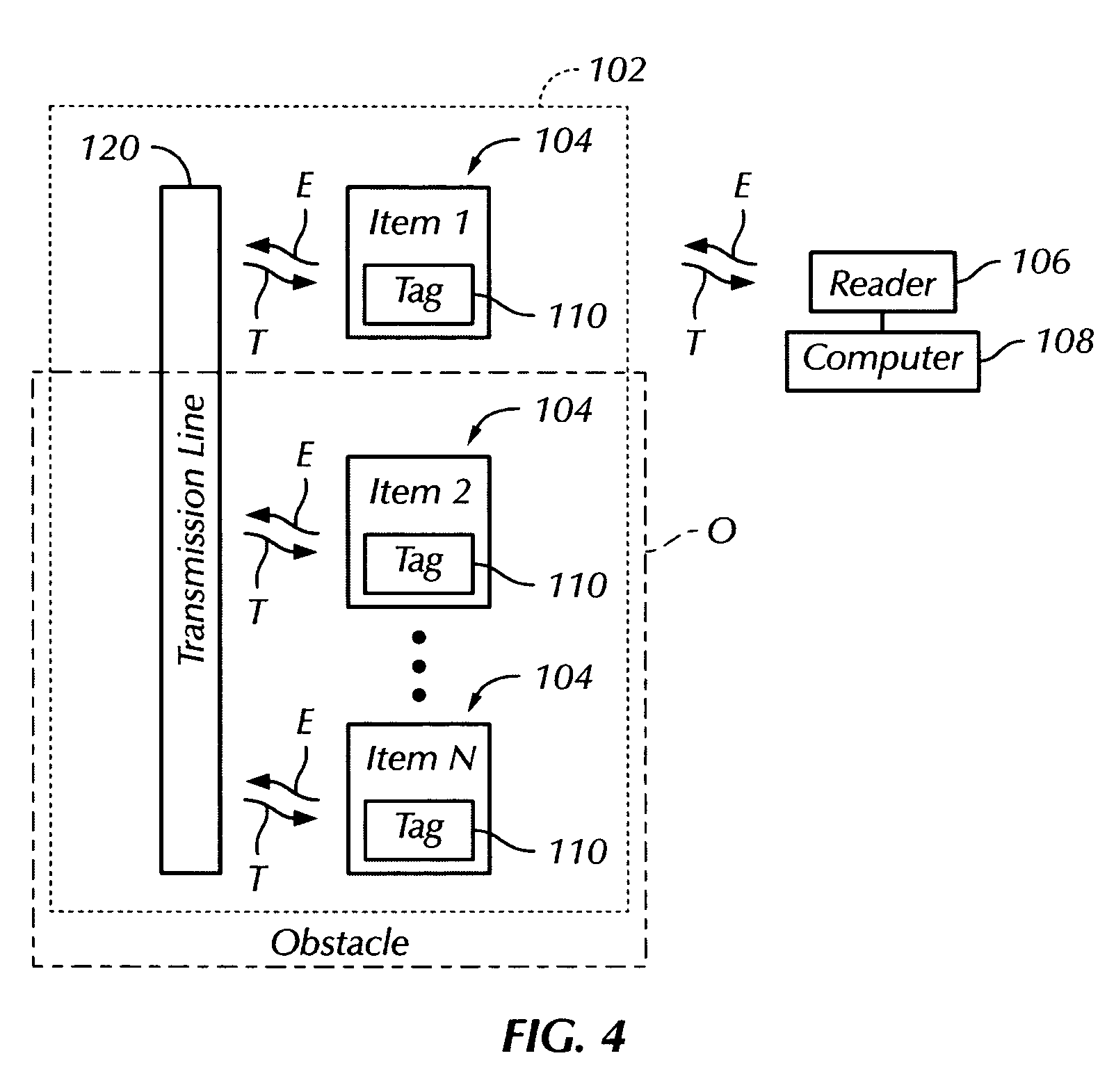
[0034] Referring more particularly to FIG. 1 of the drawings, a radio-frequency identification (RFID) system 100 enables the performance of a 100% read of a palletized load 102 that includes a plurality of RFID-tagged items 104 such as an object, box, carton, case, bottle, container, drum, or the like. In a number of embodiments, the system 100 may include a reader or interrogator 106 and a computer 108. The reader 106 transmits and receives radio-frequency (RF) energy to and from the load 102, and passes information associated with the load 102 and carried by the energy received from the load to the computer 108. The computer 108 in turn may be connected to, for example, a network, an output device, and / or a database for further processing of the information.

[0035] The system 100 includes a plurality of RFID tags 110 that are respectively mounted to each of a plurality of items 112. Each of the tags 110 includes an RFID circuit 114 that, in turn, may include a chip 116 operatively...


PUM


Abstract

Radio-frequency identification (RFID) apparatus and methodology enable a plurality of or all of the RFID tags in a stack of items such as cartons and boxes—including items that do not have a line of sight to a reader—to be read. An RFID system includes RFID tags and a transmission line. The RFID tags are mountable to items to be read and include an RFID circuit that generates tag energy when activated by activation energy from a reader. The transmission line carries activation energy from the reader and tag energy from the tags. The transmission line is positionable in operative or coupling proximately to a plurality of the tags when the plurality of the tags are mounted to items and when the items are stacked. Accordingly, when carrying activation energy from the reader, the transmission line couples with and thereby enables activation of the plurality of the tags. Further, when the plurality of the tags are activated and generating tag energy, the transmission line couples with and carries the tag energy from the plurality of the tags. The transmission line can be configured as an elongated adhesive tape-like structure that can be adhered across a plurality of RFID tags mounted to a plurality of items. The transmission line can also be disposed on an inter-item reading device that can be positioned between adjacent rows of stacked items.

Description

BACKGROUND OF THE INVENTION [0001] The present invention relates to radio-frequency identification (RFID) systems, including RFID tags and readers. The invention also relates to RFID apparatus and methodology that enable a plurality of items, such as items stacked on a pallet, to be read, including the innermost items in the stack, and even in the presence of RF intolerant material such as liquids and metals. [0002] Automatic identification is the broad term applying to a host of technologies that are used to help machines identify items or objects such as cartons, boxes, bottles, and so on. Automatic identification is often coupled with automatic data capture. Therefore, companies wanting to identify items are able to capture information about the items, to store the captured information in a computer, and to retrieve selectively the information from the computer for a variety of useful purposes, all with minimal human labor. [0003] One type of automatic identification technology i...

Claims


Application Information

Patent Timeline
Patent Type & Authority Applications(United States)
IPC IPC(8): G08B13/14
CPCG06K7/10178G06K7/10336G06K7/10346G06K19/07749G06K19/07796B65D2203/10G06K7/08G06K17/00G06K19/07G08B13/14
Inventor FORSTER, IAN JAMESHOLMAN, ANDREW W.
Owner AVERY DENNISON CORP
Why Eureka
Try Eureka