Adjustable lamp module and image projector applied with the lamp module

a technology of image projector and lamp module, which is applied in the direction of lighting and heating apparatus, instruments, lighting support devices, etc., can solve the problems of affecting affecting the quality of the image projector. , to achieve the effect of optimal presentation of the overall optical quality of the image projector, quick and easy adjustment of the lamp modul

Inactive Publication Date: 2006-07-06
QUISDA CORP
View PDF5 Cites 3 Cited by
  • Summary
  • Abstract
  • Description
  • Claims
  • Application Information

AI Technical Summary

Benefits of technology

[0008] It is therefore the object of the invention to provide an adjustable lamp module applied to an image projector for quickly and easily adjusting the lamp module, so that the illumination system is situated at an optimum illumination position and the overall optical quality of the image projector can be optimally presented.

Problems solved by technology

Therefore, how to produce an image projector to meet the consumer's high expectation of quality has become an imminent challenge to the manufacturers.
If the lamp is erroneously positioned, the problems such as weakened brightness, poor imaging quality and evenness in distribution would arise.
Typically, there is no adjustable apparatus installed in the typical image projector for adjusting the illumination system.
Once assembled, the components can no longer be adjusted.
If the lamp sleeve is made of expensive materials, the manufacturing cost can not be decreased if the yield rate is low.
Also, it is diffucult to optimizing the optical quality of the image projector and lack of flexibility of assembly without the adjustable lamp.
According to the conventional method of mounting the lamp on the housing, the adjustment method is inflexible and the optimization of image projector is hard to achieve.

Method used


Image

  • Adjustable lamp module and image projector applied with the lamp module
  • Adjustable lamp module and image projector applied with the lamp module
  • Adjustable lamp module and image projector applied with the lamp module

Examples


first embodiment

[0021] In the first embodiment, the lamp module adjustable along the y-axis direction is illustrated in detail.

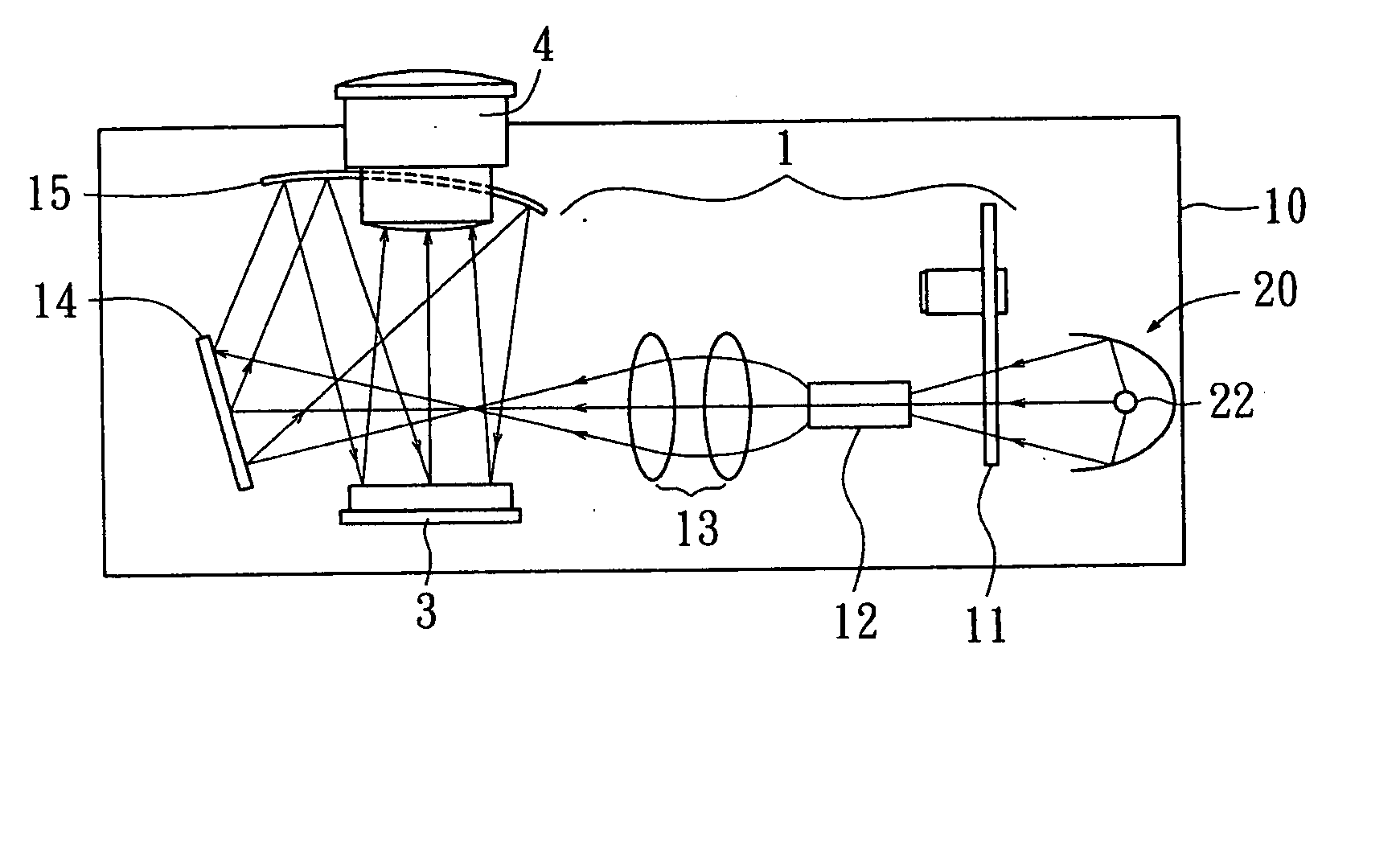
[0022] Referring to FIG. 1A, a diagram of an image projector according to an embodiment of the invention is shown. The image projector uses a housing 10 to be mounted with the main components including a lamp module 20, an optical assembly 1, an imaging component 3 and a lens module 4. When the image projector functions, a beam of light is generated by a lamp 22 of a lamp module 20, and then projected on the imaging component 3 after passing the optical assembly 1 and then reflected to the lens 4. The image of the imaging device is projected onto the screen via the lens 28 while the imaging component overlaps with the illumination region generated from the beam of light projected to the imaging component. The optical assembly includes a color wheel 11, a uniform tube 12, a condenser 13, a fold mirror 14 and a concave mirror 15 for instance. Examples of the imaging componen...

second embodiment

[0029] In the second embodiment, the lamp module adjustable along the x-axis direction is illustrated in detail. Additionally, the same components depicted in the first and second embodiments are denoted by the same reference numbers.

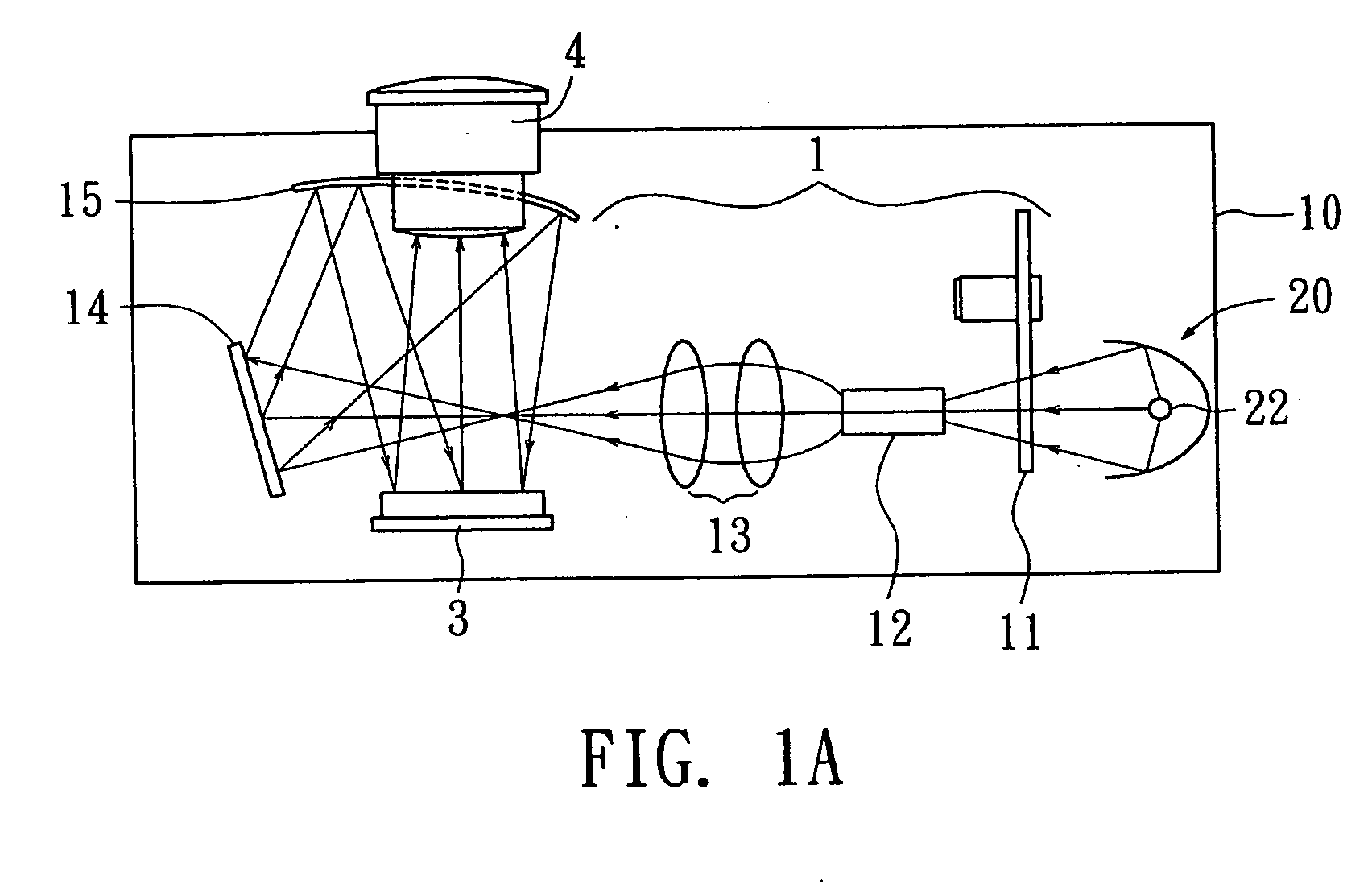
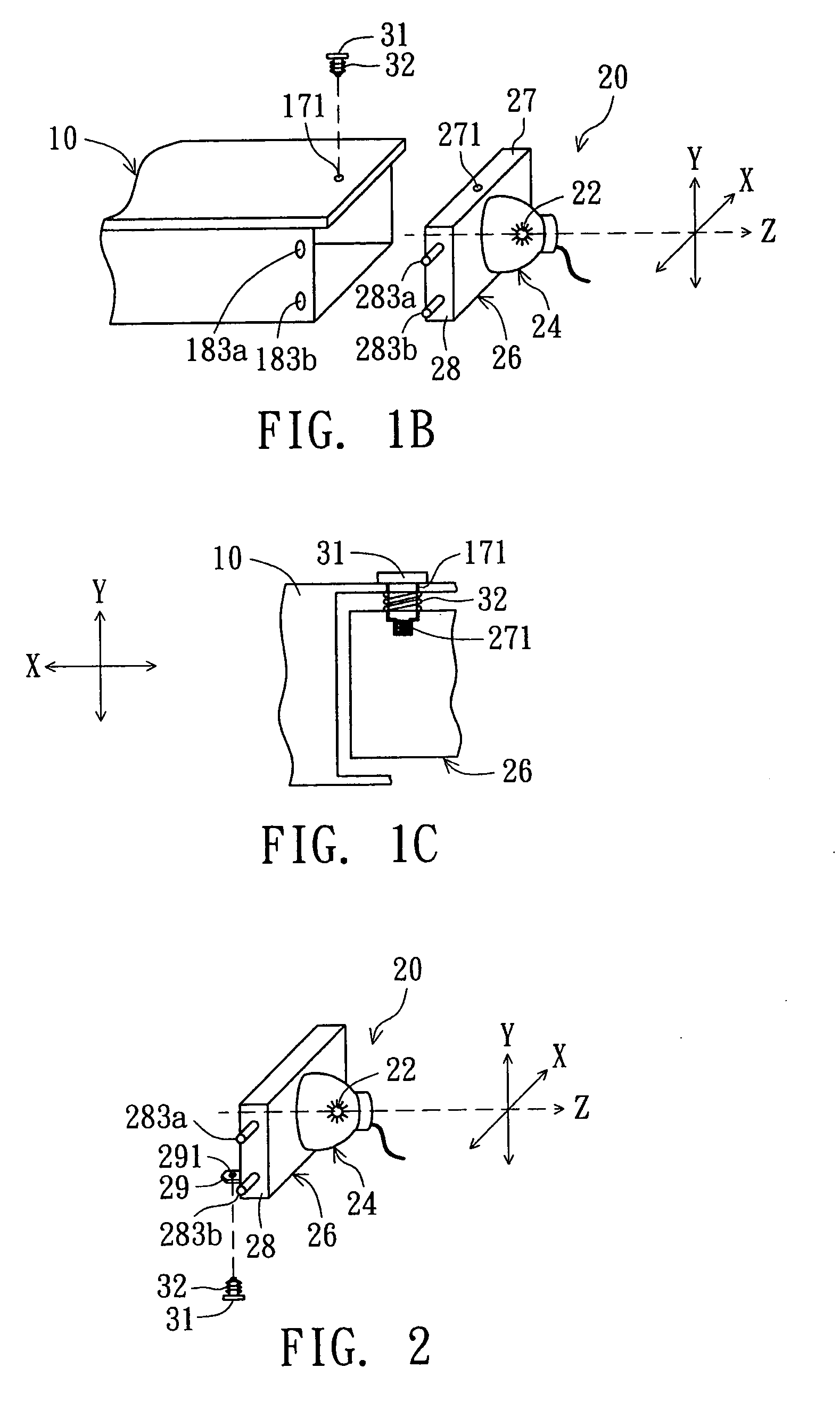
[0030] As shown in FIG. 3A, the lamp module 20 includes a lamp 22 and a lamp sleeve 24. A plane perpendicular to an optical axis (the z-axis) of the lamp 22 is defined by an x-axis direction and a y-axis direction mutually perpendicular to each other. The lamp 22 is mounted within the lamp sleeve 24. A positioning piece 26 situated at one end of the lamp sleeve 24 is used for mounting the lamp sleeve 24 on the housing 10. The lamp sleeve 24 and the positioning piece 26 are preferably formed according to one-piece molding method. Like the first embodiment, in the second embodiment, the first surface 27 and the second surface 28 of the positioning piece 26 are respectively parallel to the x-axis direction and the y-axis direction. At least one of the fir...

third embodiment

[0035] In the third embodiment, the lamp module adjustable along both the x-axis direction and the y-axis direction is illustrated in detail. During adjustment, the position of the lamp module in one of the two axes is aligned first, and then the position of the lamp module in another axis is aligned.

[0036] As shown in FIG. 5, the plane defined by an x-axis direction and a y-axis direction mutually perpendicular to each other is perpendicular to an optical axis (the z-axis). A lamp 22 is mounted within a lamp sleeve 24, and a positioning piece 26 is formed at one end of the lamp sleeve 24 for mounting the lamp sleeve 24 on the housing 10. The lamp sleeve 24 and the positioning piece 26 are preferably formed according to one-piece molding method. The first surface 27 and the second surface 28 of the positioning piece 26 are respectively parallel to the x-axis direction and the y-axis direction. The third embodiment combines the designs of the first and second embodiments to achieve ...


PUM


Abstract

A lamp module mounted on a housing is provided. The lamp module includes a lamp and a lamp sleeve. The plane perpendicular to an optical of the lamp has an x-axis direction and a y-axis direction mutually perpendicular to each other. The lamp is mounted within the lamp sleeve, and a positioning piece is formed at one end of the lamp sleeve for mounting the lamp sleeve on the housing. The positioning piece at least includes a first surface and a second surface respectively parallel to the x-axis direction and the y-axis direction. At least one of the first surface and the second surface is equipped with an adjustable apparatus for adjusting the alignment of the lamp by moving the positioning piece along the direction(s) of the x-axis or/and the y-axis. The adjustable apparatus comprises a positioning component, a fastener and an elastic component.

Description

[0001] This application claims the benefit of Taiwan application Serial No. 094100102, filed Jan. 3, 2005, the subject matter of which is incorporated herein by reference. BACKGROUND OF THE INVENTION [0002] 1. Field of the Invention [0003] The invention relates in general to an adjustable lens module, and more particularly to an adjustable lens module and an image projector applied with the same. [0004] 2. Description of the Related Art [0005] Along with a higher living standard is desired, home theater is gaining a wider and wider popularity. The image projector used in a home theater, such as a back projection TV for instance, is now experiencing a fierce competition. Therefore, how to produce an image projector to meet the consumer's high expectation of quality has become an imminent challenge to the manufacturers. [0006] An image projector mainly includes a light source, an optical assembly, an imaging device and a lens module. The image projector functions by enabling the beam ...

Claims


Application Information

Patent Timeline
Patent Type & Authority Applications(United States)
IPC IPC(8): F21V21/00
CPCG03B21/14G03B21/2046G03B21/145
Inventor LIN, YING-FANGCHEN, YUEH-JEN
Owner QUISDA CORP
Why Eureka
Try Eureka