Adjustable lamp module and image projector applied with the lamp module
a technology of image projector and lamp module, which is applied in the direction of lighting support devices, instruments, lighting and heating apparatus, etc., can solve the problems of affecting affecting the quality of the image projector. , to achieve the effect of optimal presentation of the overall optical quality of the image projector, quick and easy adjustment of the lamp modul
- Summary
- Abstract
- Description
- Claims
- Application Information
AI Technical Summary
Benefits of technology
Problems solved by technology
Method used
Image
Examples
first embodiment
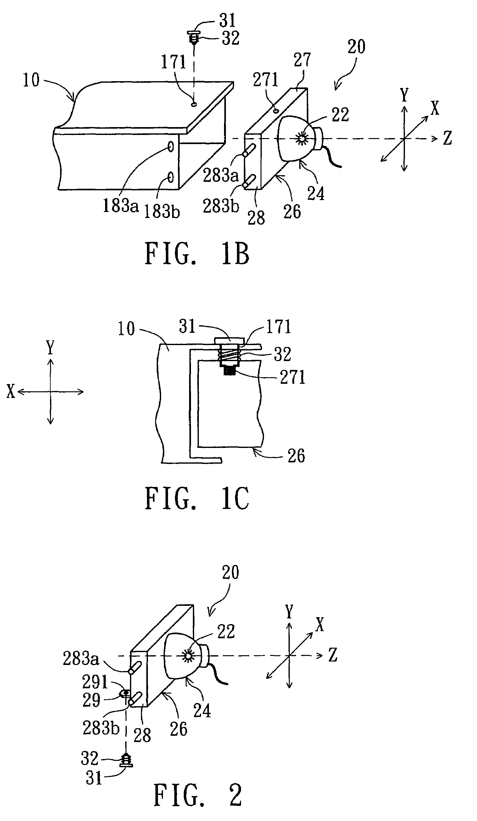
[0021]In the first embodiment, the lamp module adjustable along the y-axis direction is illustrated in detail.
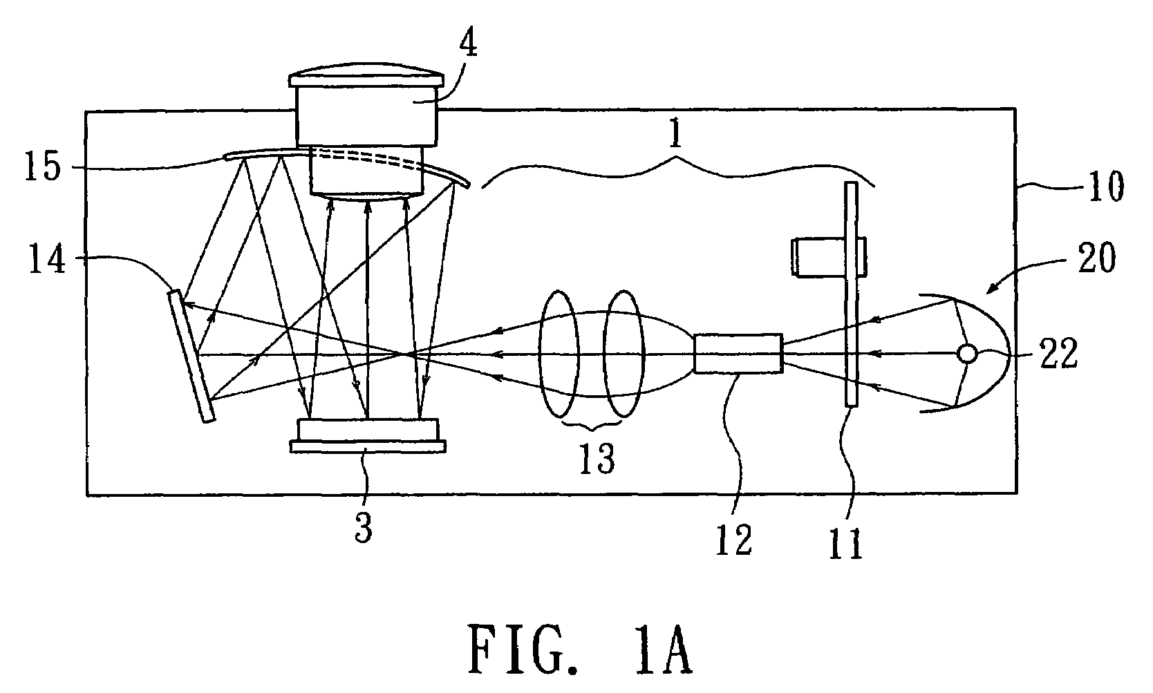
[0022]Referring to FIG. 1A, a diagram of an image projector according to an embodiment of the invention is shown. The image projector uses a housing 10 to be mounted with the main components including a lamp module 20, an optical assembly 1, an imaging component 3 and a lens module 4. When the image projector functions, a beam of light is generated by a lamp 22 of a lamp module 20, and then projected on the imaging component 3 after passing the optical assembly 1 and then reflected to the lens 4. The image of the imaging device is projected onto the screen via the lens 28 while the imaging component overlaps with the illumination region generated from the beam of light projected to the imaging component. The optical assembly includes a color wheel 11, a uniform tube 12, a condenser 13, a fold mirror 14 and a concave mirror 15 for instance. Examples of the imaging component 3...
second embodiment
[0029]In the second embodiment, the lamp module adjustable along the x-axis direction is illustrated in detail. Additionally, the same components depicted in the first and second embodiments are denoted by the same reference numbers.
[0030]As shown in FIG. 3A, the lamp module 20 includes a lamp 22 and a lamp sleeve 24. A plane perpendicular to an optical axis (the z-axis) of the lamp 22 is defined by an x-axis direction and a y-axis direction mutually perpendicular to each other. The lamp 22 is mounted within the lamp sleeve 24. A positioning piece 26 situated at one end of the lamp sleeve 24 is used for mounting the lamp sleeve 24 on the housing 10. The lamp sleeve 24 and the positioning piece 26 are preferably formed according to one-piece molding method. Like the first embodiment, in the second embodiment, the first surface 27 and the second surface 28 of the positioning piece 26 are respectively parallel to the x-axis direction and the y-axis direction. At least one of the first ...
third embodiment
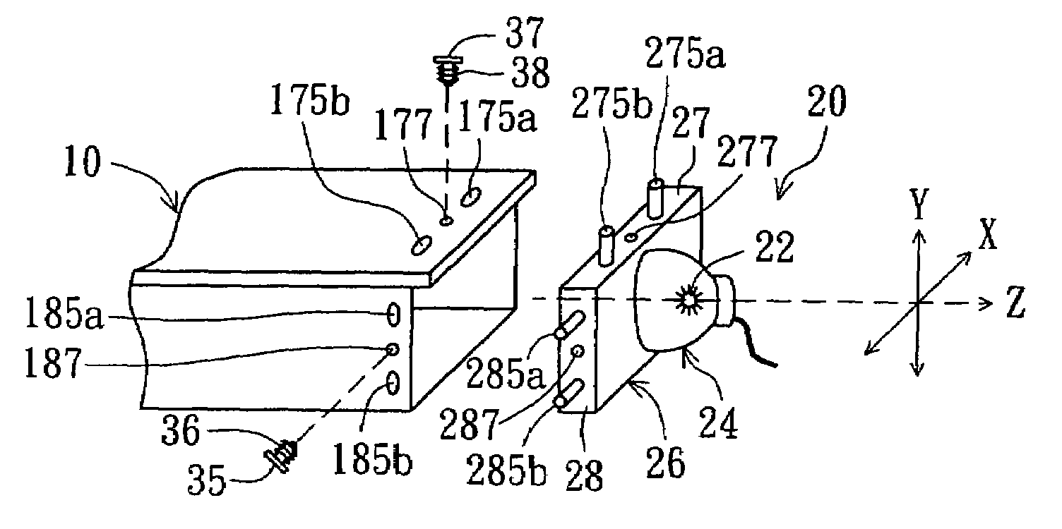
[0035]In the third embodiment, the lamp module adjustable along both the x-axis direction and the y-axis direction is illustrated in detail. During adjustment, the position of the lamp module in one of the two axes is aligned first, and then the position of the lamp module in another axis is aligned.
[0036]As shown in FIG. 5, the plane defined by an x-axis direction and a y-axis direction mutually perpendicular to each other is perpendicular to an optical axis (the z-axis). A lamp 22 is mounted within a lamp sleeve 24, and a positioning piece 26 is formed at one end of the lamp sleeve 24 for mounting the lamp sleeve 24 on the housing 10. The lamp sleeve 24 and the positioning piece 26 are preferably formed according to one-piece molding method. The first surface 27 and the second surface 28 of the positioning piece 26 are respectively parallel to the x-axis direction and the y-axis direction. The third embodiment combines the designs of the first and second embodiments to achieve the...
PUM
 Abstract
Description
Claims
Application Information
 - R&D
- Intellectual Property
- Life Sciences
- Materials
- Tech Scout
- Unparalleled Data Quality
- Higher Quality Content
- 60% Fewer Hallucinations
Browse by: Latest US Patents, China's latest patents, Technical Efficacy Thesaurus, Application Domain, Technology Topic, Popular Technical Reports.
© 2025 PatSnap. All rights reserved.Legal|Privacy policy|Modern Slavery Act Transparency Statement|Sitemap|About US| Contact US: help@patsnap.com


