Exhausting and cooling system for cooking utensil

a technology of exhausting and cooling system and cooking utensils, which is applied in the direction of gaseous heating fuel, combustion type, stoves or ranges, etc., can solve the problems of inconvenience for users, difficulty in installing cooking utensils, and inconvenience for users

Inactive Publication Date: 2006-07-13
SAMSUNG ELECTRONICS CO LTD
View PDF5 Cites 49 Cited by
  • Summary
  • Abstract
  • Description
  • Claims
  • Application Information

AI Technical Summary

Benefits of technology

[0011] Therefore, one aspect of the invention is to provide an exhausting and cooling system for a cooking utensil, which simultaneously exhausts gas or odors generated during a cooking process and cools the lower portion of a grill.
[0012] Another aspect of the invention is to provide an exha

Problems solved by technology

When food is cooked using the grill for the cooking utensil, waste or oil is dropped from the food onto a reflecting plate or a pan placed in the lower portion of the grill, and is burned because the reflecting plate or the pan is heated by a heater, thereby generating smoke or odors, thus inconveniencing users.
In this case, the water must be refilled or replaced with new water, thereby causing inconvenience to the users.
That is, in order to install the exhaust duct extended to the outsid

Method used


Image

  • Exhausting and cooling system for cooking utensil
  • Exhausting and cooling system for cooking utensil
  • Exhausting and cooling system for cooking utensil

Examples


first embodiment

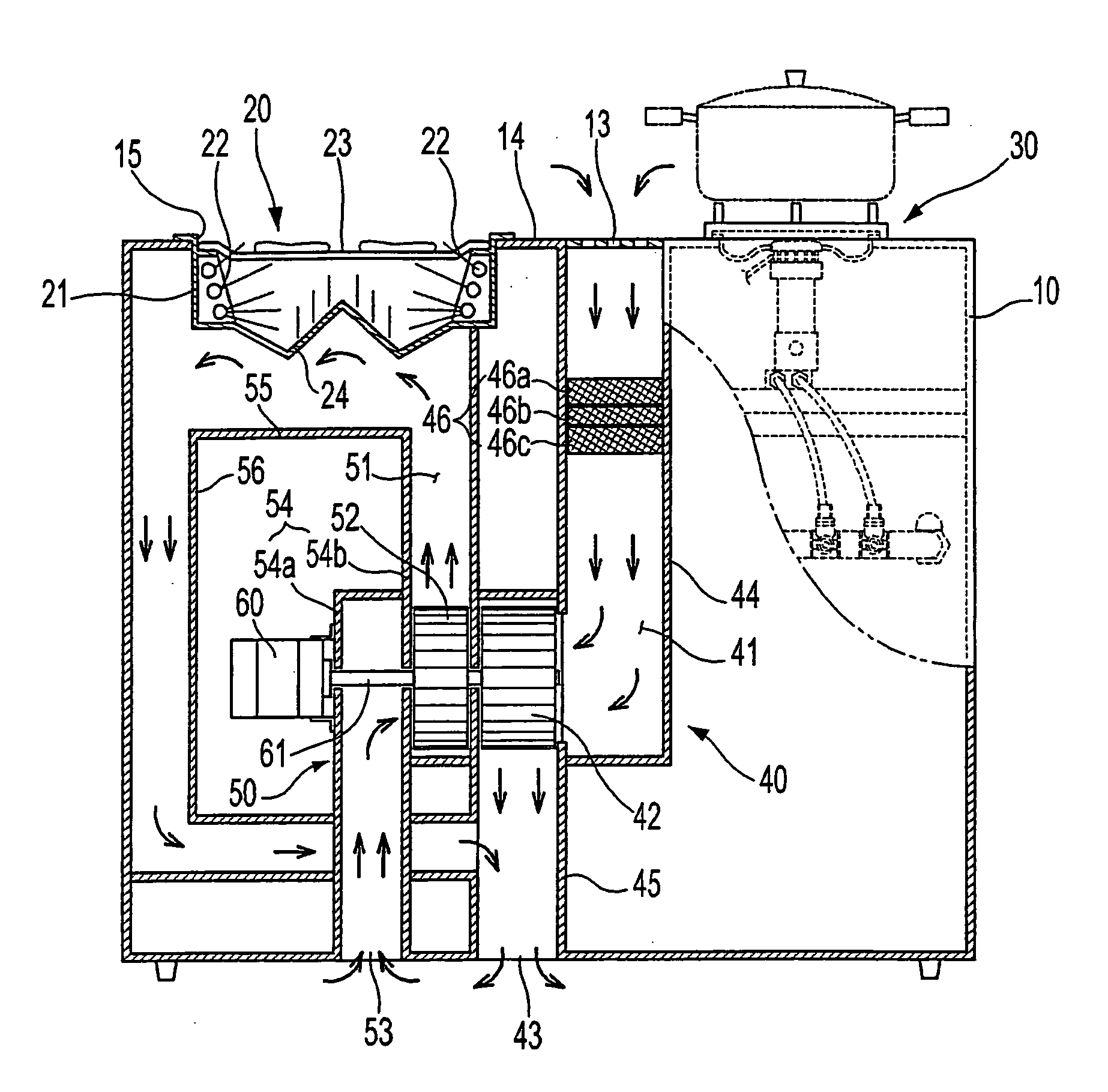
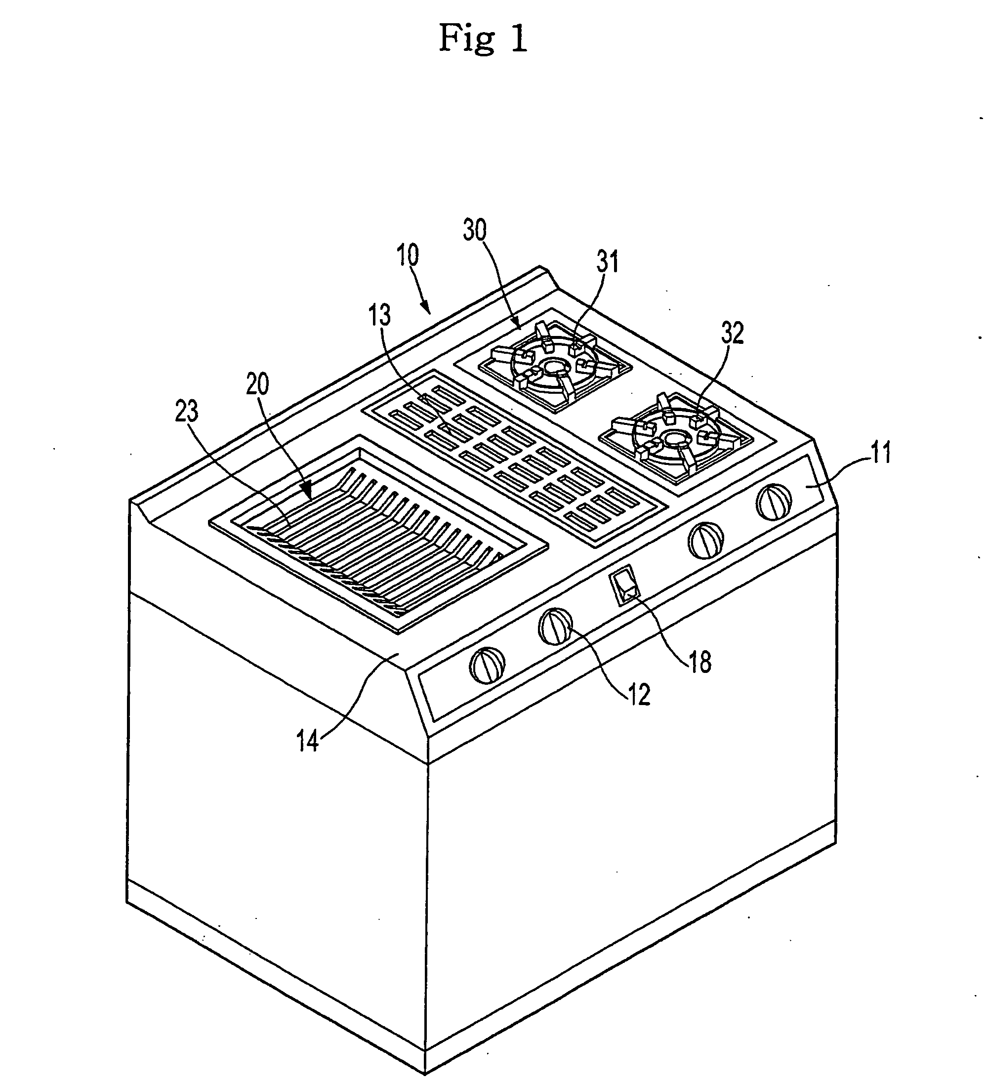
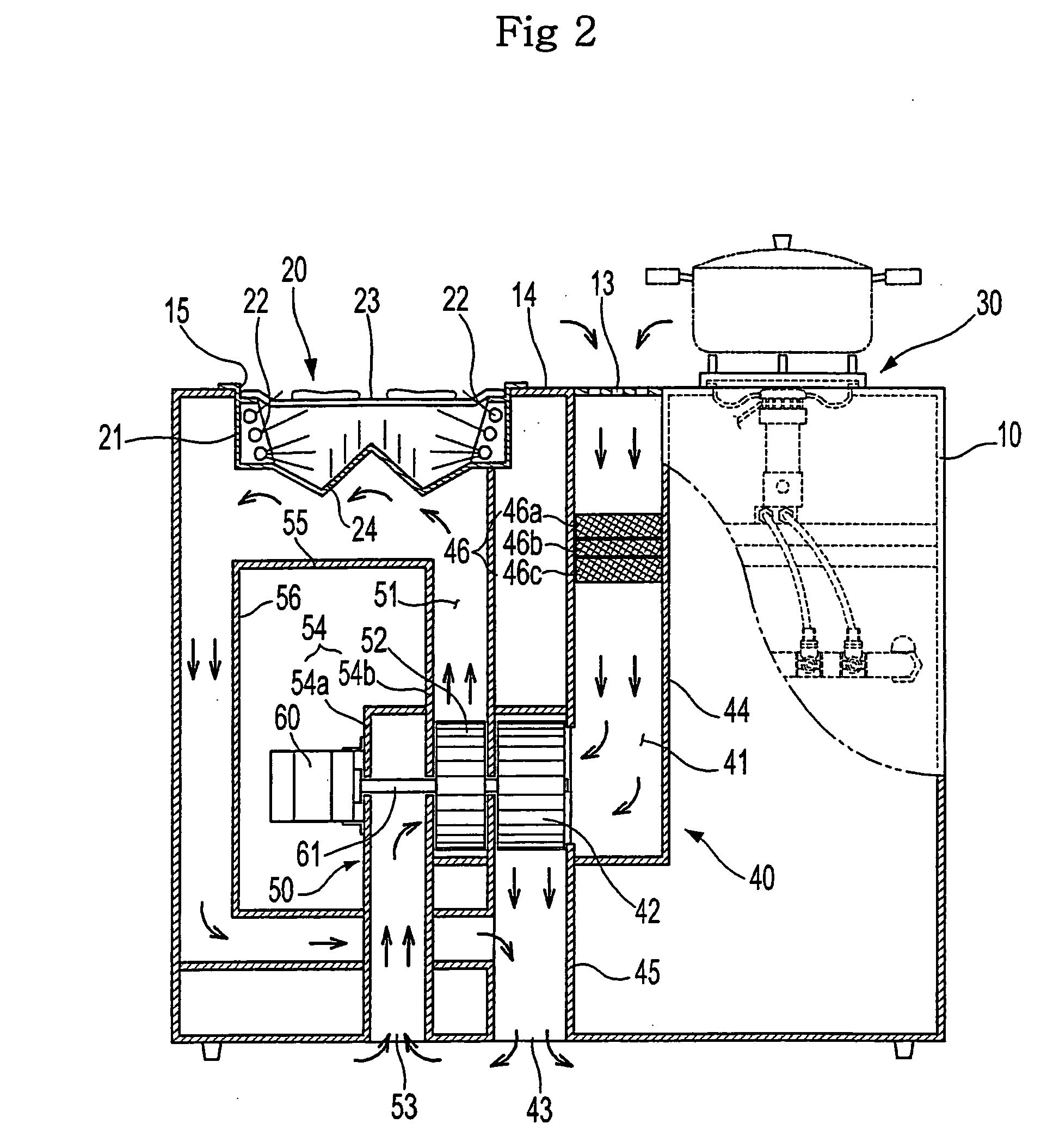
[0032]FIGS. 1 and 2 illustrate a cooking utensil in accordance with the present invention. As shown in FIGS. 1 and 2, the cooking utensil of this embodiment includes a main body 10 provided with a grill unit 20 installed at one side of the upper surface thereof and a gas range 30 having a plurality of burners 31 and 32 installed at the other side of the upper surface thereof. An operating panel 11 having a plurality of operating switches 12 for controlling the operation of the cooking utensil is installed on the upper part of the front surface of the main body 10.

[0033] Inlets 13 for sucking gas, smoke, and odors generated during a cooking process are formed through the central part of the upper surface of the main body 10, i.e., between the grill unit 20 and the gas range 30. As shown in FIG. 2, an exhausting device 40 for exhausting air (air including gas, smoke, and odors) sucked into the inlets 13, and a cooling device 50 for blowing external air to a lower portion of the grill ...

third embodiment

[0045]FIG. 4 is a sectional view illustrating the internal configuration for a cooking utensil in accordance with the present invention. A cooling heat exchanger 70 for cooling and dehumidifying the exhausted air is installed in the cooking utensil of this embodiment close to the outlet of the exhaust channel 41.

[0046] The cooling heat exchanger 70 is a fin-tube heat exchanger through which cooling water flows. That is, a cooling water supply pipe 73 for supplying cooling water from an external water supply source to the cooling heat exchanger 70 and a cooling water discharge pipe 74 for discharging the water passed through the cooling heat exchanger 70 to the outside are connected to the cooling heat exchanger 70.

[0047] A flow control valve 75 for controlling the supply of the cooling water to the cooling heat exchanger 70 is installed in the cooling water supply pipe 73. The flow control valve 75 is configured such that the channel of the flow control valve 75 is opened or closed...


PUM


Abstract

An exhausting and cooling system for a cooking utensil, which exhausts gas or smoke generated during a cooking process and cools a lower portion of a grill. The exhausting and cooling system for the cooking utensil, which has a main body provided with a grill unit mounted on the upper surface thereof, includes an exhaust channel and an exhaust fan for inhaling air around the grill unit and exhausting the air downwardly; and a cooling channel and a cooling fan for blowing external air to the lower portion of the grill unit to cool the lower portion of the grill unit.

Description

CROSS-REFERENCE TO RELATED APPLICATIONS [0001] This application claims the benefit of Korean Patent Application No. 2005-3393, filed Jan. 13, 2005, and Korean Patent Application No. 2005-8141, filed Jan. 28, 2005, in the Korean Intellectual Property Office, the disclosure of which is incorporated herein by reference. BACKGROUND OF THE INVENTION [0002] 1. Field of the Invention [0003] The present invention relates to an exhausting and cooling system for a cooking utensil, and more particularly, to an exhausting and cooling system for a cooking utensil, which exhausts gas or smoke generated during a cooking process and cools a lower portion of a grill. [0004] 2. Description of the Related Art [0005] U.S. Pat. No. 5,619,982 discusses a cooking utensil having an exhausting device for exhausting gas, smoke, and food odors generated during a cooking process. [0006] The disclosed cooking utensil includes a main body provided with a general gas range at one side of the upper surface thereof...

Claims


Application Information

Patent Timeline
IPC IPC(8): F24C15/20
CPCF24C15/2042
Inventor KIM, DONG WONNA, SEON UKLEE, BYOUNG INWU, SEONG JEKIM, CHUL
Owner SAMSUNG ELECTRONICS CO LTD
Why Eureka
Try Eureka