
Rock bolt

a technology of bolts and bolts, applied in the field of rock bolts, can solve the problems of inability to use assembly in more confined areas, inability to achieve adequate mixing of two component resins, and inability to use externally mounted resin cartridges

Inactive Publication Date: 2006-07-13
DYWIDAG SYST INT PTY LTD
View PDF11 Cites 35 Cited by
  • Summary
  • Abstract
  • Description
  • Claims
  • Application Information

AI Technical Summary

Problems solved by technology

As a result, such an assembly cannot be utilised in more confined areas such as mines or tunnels having a low roof height, as there is insufficient room to manoeuvre the assembly on a rock bolt installation rig and align it with the hole in which the assembly is to be inserted.
Further, externally mounted resin cartridges are prone to danage during maneuvering of the rock bolt installation rig within the mine / tunnel and during installation of the rock bolt assembly itself.
The static mixing device and cartridge rupturing device, are, however subject to blockage from fragments of the ruptured casing of the resin cartridge, thereby inhibiting the flow and adequate mixing of the two component resin.
Further, given that the plunger typically needs to be mounted in the rock bolt prior to insertion with a standard rock bolt installation rig, the assembly of the rock bolt and plunger suffers from the same disadvantages of excess length discussed above in relation to rock bolt assemblies having externally mounted resin cartridges.

Method used


Image

  • Rock bolt
  • Rock bolt
  • Rock bolt

Examples


Embodiment Construction

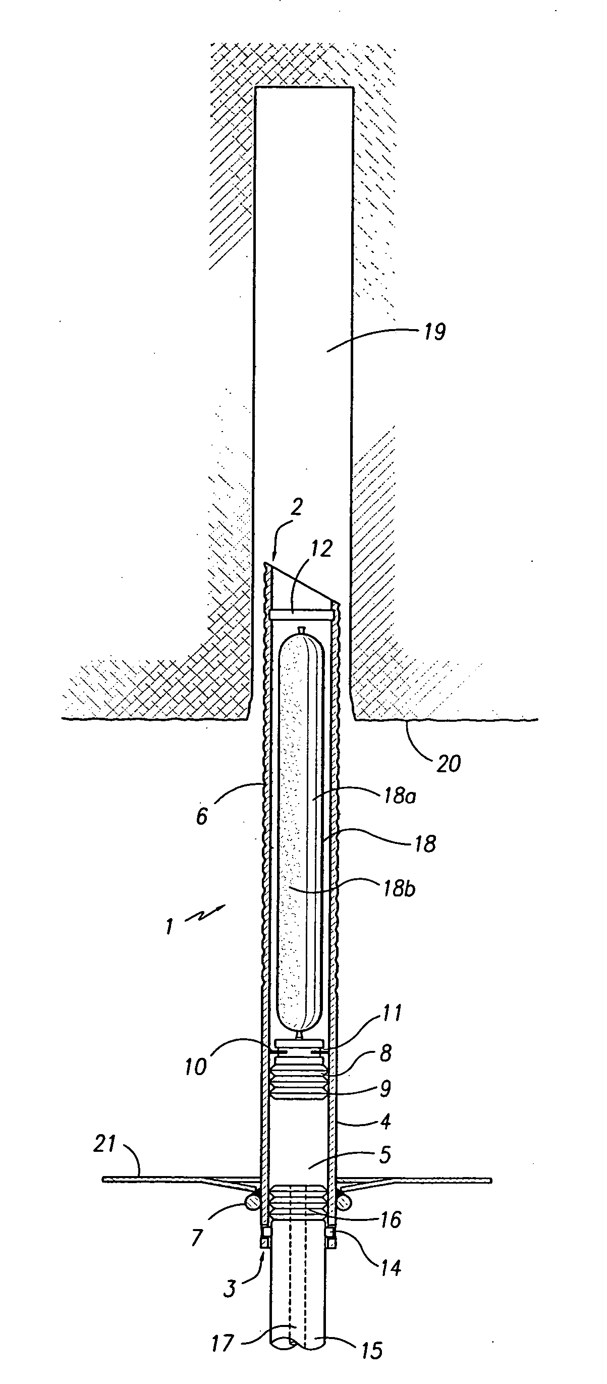
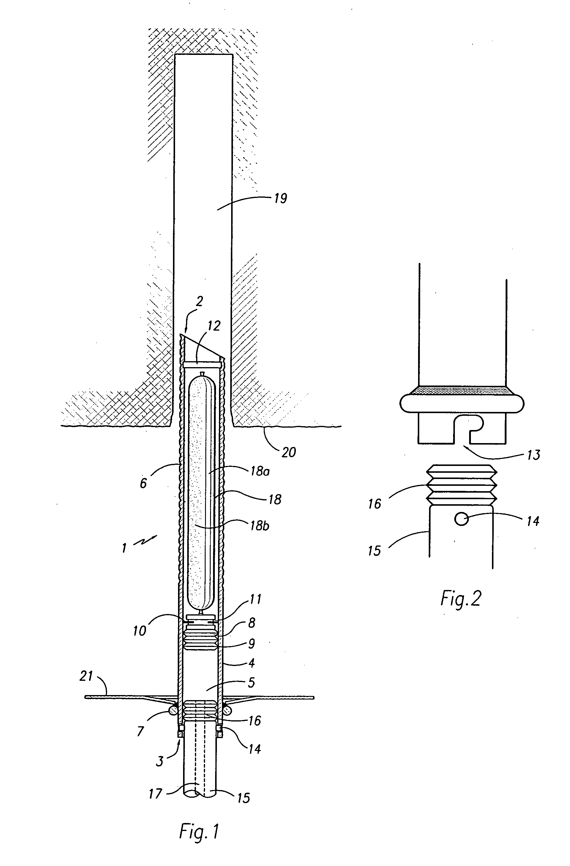
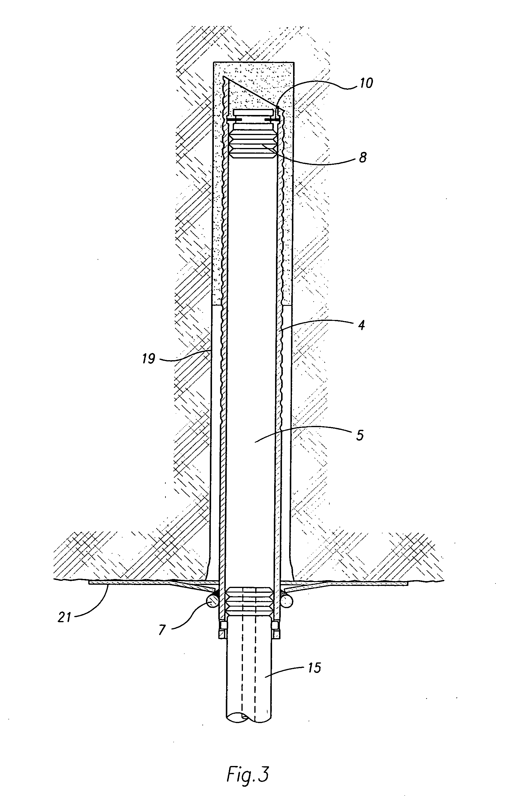
[0054] Referring specifically to FIGS. 1 to 3, a rock bolt 1 has a first (upper) end 2 and a second (lower) end 3. The rock bolt has a tubular body 4 defining a tubular bore 5. The bore 5 has a substantially constant cross-section throughout its length. The tubular body 4 is typically formed of a steel tube. The tubular body 4 here extends from an opening at the rock bolt first end 2 to the rock bolt second end 3. Helical thread like deformations 6 are formed on the outer surface of the tubular body 4, typically by a rolling process.

[0055] A bolt head 7 is located at or adjacent the rock bolt second end 3. Here the bolt head 7 is in the form of an annular collar fixed to the tubular body 4, typically by welding.

[0056] A plug 8 is mounted in the bore 5. The plug 8 is displaceable along the bore 5 and is configured to sealingly engage the tubular body 4 so as to seal the bore 5. The plug 8 is typically formed of an elastomeric material with a series of annular ridges 9 to ensure int...


PUM


Abstract

A rock bolt (1) comprises a tubular body (4) defining a tubular bore (5) for receiving an adhesive or cement filled cartridge (18). A plug (8) is mounted in the bore (5). The plug (8) is displaceable along the bore (5) and sealingly engages the tubular body (4). A bolt head (7) is located at or adjacent a second end (3) of the rock bolt (1). A detent arrangement (10, 12) restrains the plug (8) in a position adjacent an opening at the first end (2) of the rock bolt (1).

Description

FIELD OF THE INVENTION [0001] The present invention relates to mining equipment, and in particular relates to a rock bolt for securing the roof or wall of a mine, tunnel or other ground excavation. BACKGROUND OF THE INVENTION [0002] A known method of installing a resin grouted rock bolt to secure the roof or wall of an underground mine, tunnel or other ground excavation involves mounting a two component resin filled cartridge on the upper end of the rock bolt and inserting the assembled resin cartridge and rock bolt into a hole drilled into the rock face. When the resin cartridge reaches the top end of the hole, the upper end of the rock bolt pierces the resin cartridge, enabling the two resin components to be mixed. Mixing of the resin components is typically achieved by rotating the rock bolt within the hole. The mixed resin sets in the annular cavity between the upper end portion of the rock bolt and the wall of the hole in the rock face, thereby anchoring the upper end of the ro...

Claims


Application Information

Patent Timeline
IPC IPC(8): E21D21/00
CPCE21D20/026
Inventor RATAJ, MIECZYSLAW S.BOYCHUK, ANDREW
Owner DYWIDAG SYST INT PTY LTD
Features
  • Generate Ideas
  • Intellectual Property
  • Life Sciences
  • Materials
  • Tech Scout
  • Unparalleled Data Quality
  • Higher Quality Content
  • 60% Fewer Hallucinations
Learn More