
In-wheel motor

Inactive Publication Date: 2006-07-20
MITSUBISHI MOTORS CORP
View PDF5 Cites 52 Cited by
  • Summary
  • Abstract
  • Description
  • Claims
  • Application Information

AI Technical Summary

Problems solved by technology

Hence, circumferential velocity around the bearing is very high, which causes durability of the bearing, and therefore, reliability of the in-wheel motor to lower.

Method used


Image

  • In-wheel motor
  • In-wheel motor
  • In-wheel motor

Examples


Embodiment Construction

[0016] An in-wheel motor according to a first embodiment of the present invention will be described below.

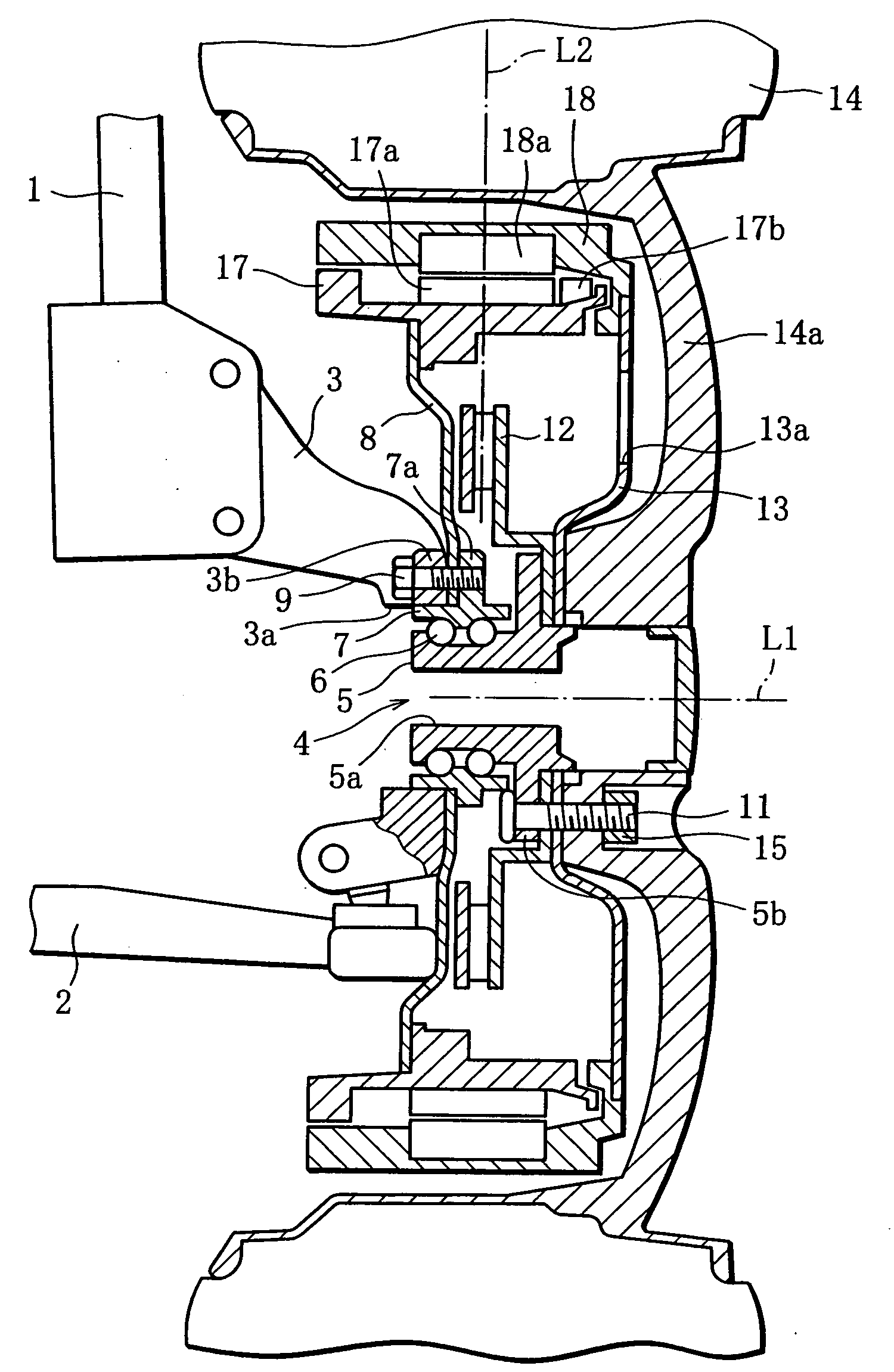
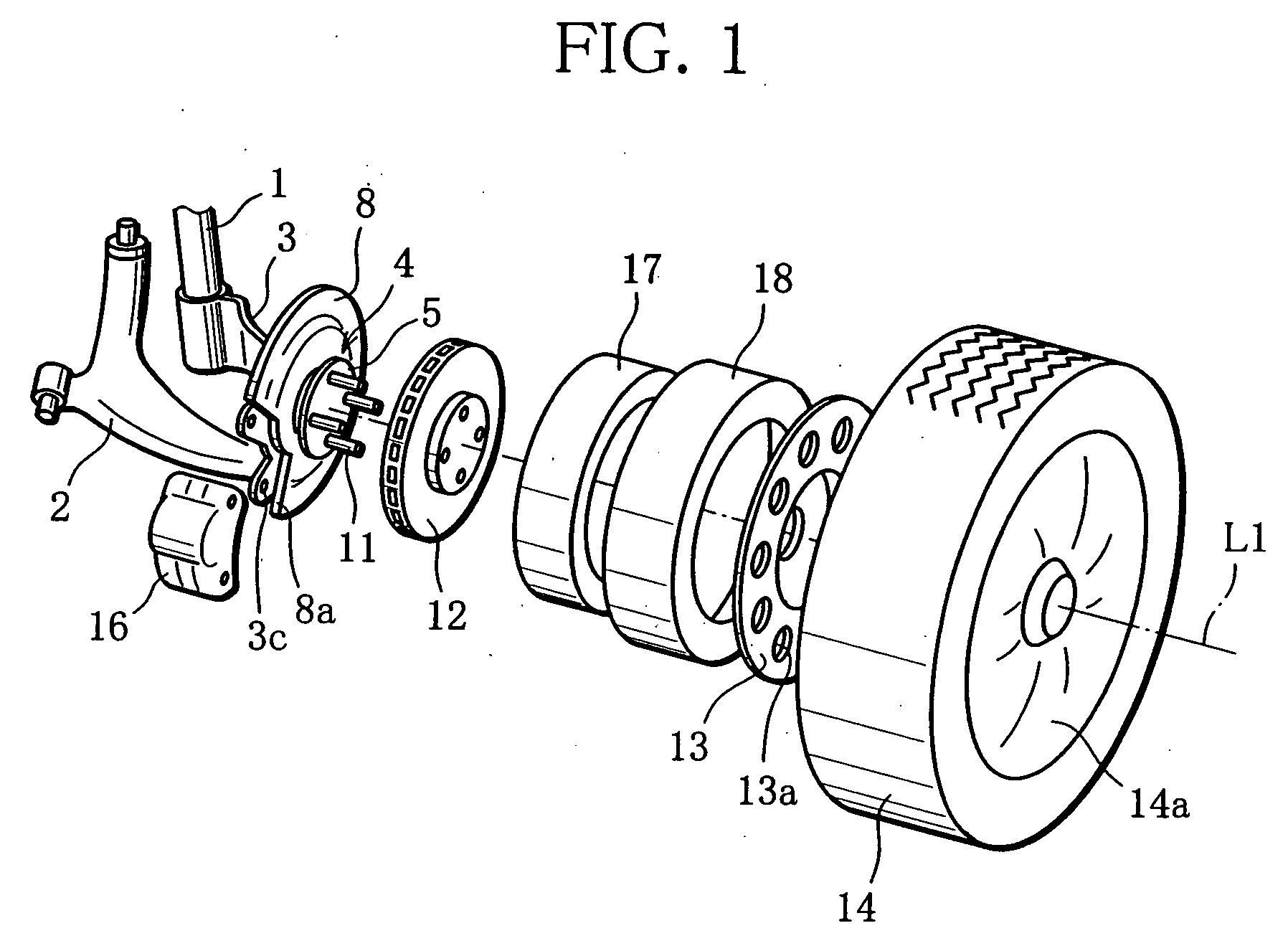
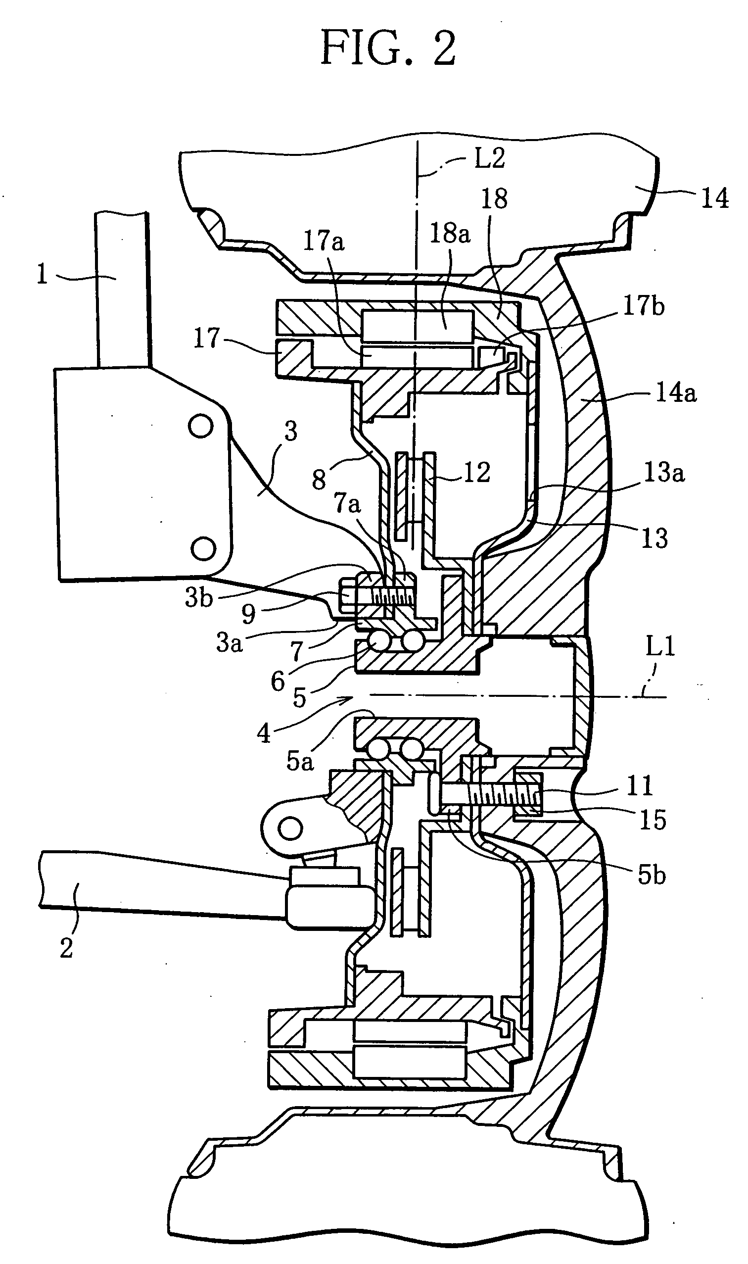
[0017] In a vehicle, all the four wheels have an in-wheel motor, and the in-wheel motor provided in the front wheel and the in-wheel motor provided in the rear wheel are almost the same in structure and fitting structure. Hence, the in-wheel motor provided in the front wheel will be described, referring to an oblique view in FIG. 1 and a cross-sectional view in FIG. 2.

[0018] A knuckle 3 (non-rotating part) is connected with the lower end of a strut 1 and the outer end of a lower arm 2, swingably, where the strut 1 and the lower arm 2 form parts of a front-wheel suspension of a vehicle. A hub unit 4 is fitted in a knuckle hole 3a in the knuckle 3. The hub unit 4 includes an outer hub (fixed component) 7 and an inner hub (rotating component) 5 rotatably fitted inside the outer hub 7 with a bearing 6 between. The outer hub 7 is fitted in the knuckle hole 3a in the knuckle 3 and t...


PUM


Abstract

A front wheel is rotatably fitted to a knuckle of a suspension by means of a hub unit. While a stator bracket, which is fitted to an outer hub of the hub unit fixed to the knuckle, supports an annular stator, a rotor bracket, which is fitted to an inner hub of the hub unit to which the front wheel is fixed, supports an annular rotor, outside the stator. Rotation of the rotor is guided by a bearing of the hub unit.

Description

BACKGROUND OF THE INVENTION [0001] 1. Field of the Invention [0002] This invention relates to an in-wheel motor provided in a wheel rim of a vehicle to drive a driving wheel to rotate. [0003] 2. Description of the Related Art [0004] The in-wheel motor provided in a wheel rim of a vehicle to directly drive a driving wheel is used widely, particularly in relatively small-size vehicles such as forklifts and golf carts, since it provides various advantages such that the space required in a vehicle body can be reduced, that a transmission and a differential gear unit can be omitted, and that a drive shaft can be omitted when an independent suspension is adopted. Various structures are known for this type of in-wheel motor. As one example, an in-wheel motor having a stator and a rotor arranged like a double ring is proposed, for example, in Japanese Unexamined Patent Publication No. 2004-161189 (referred to as “Patent Document 1”). [0005] To incorporate the in-wheel motor disclosed in Pat...

Claims


Application Information

Patent Timeline
IPC IPC(8): H02K9/00
CPCB60K6/26B60K6/48B60K7/0007B60K2007/0038B60K2007/0092H02K7/14H02K9/06Y02T10/6221Y02T10/641B60L2220/44B60L2220/50Y02T10/62Y02T10/64
Inventor MAEDA, AKIRAHAYAKAWA, HIROYUKITANEDA, RYOJI
Owner MITSUBISHI MOTORS CORP
Features
  • Generate Ideas
  • Intellectual Property
  • Life Sciences
  • Materials
  • Tech Scout
  • Unparalleled Data Quality
  • Higher Quality Content
  • 60% Fewer Hallucinations
Learn More