Plug connector with mating protection and alignment means

a technology of protection and alignment means, applied in the field of cable connectors, can solve problems such as circuit board failure, large guide frame, and broken signal pathway

Active Publication Date: 2006-07-20
MOLEX INC
View PDF23 Cites 120 Cited by
  • Summary
  • Abstract
  • Description
  • Claims
  • Application Information

AI Technical Summary

Benefits of technology

[0017] The guide member that is used with the receptacle connector may also include an extension in the form of a press, or spring, arm that extends preferably toward and over the top surface of the receptacle connector plate thereof. A slot, or channel, may be formed on the top surface of the plug connector second flange and this channel, receives a portion of the guide member press arm, preferably a detent or the like so that an audible or tactile click may be heard or felt when the plug connector properly mated to the receptacle connector. The channel in the top flange assist in keeping the top flange in place over a portion of the top surface of the receptacle connector.

Problems solved by technology

A well-known problem with connecting cables to circuit board-mounted connectors is the tendency for the cable's weight and movement to loosen the points of attachment of the receptacle connector to the circuit board, thereby breaking signal pathways and causing the circuit board to fail.
However, such guide frames are large and take up valuable space on the circuit board that could be used for additional circuits or terminations.
Additionally, such guide frames are typically die cast and are prone to breakage when dropped.
Problems also arise when mating such plug connectors to their associated receptacle connectors in that in small, confined spaces, it is difficult to orient the plug for proper mating and in small spaces debris and contaminants may easily come into contact with the receptacle connector terminals.
Connector receptacle strain is also a problem and may be caused by the weight, size and movement of the cable(s).
Still further, a connector plug and its mating connector receptacle can sometimes be misaligned with respect to each other, needlessly complicating an assembly process and in high-speed connectors, portions of terminals are usually exposed to the exterior of the connector housing, where the terminals may become contaminated.

Method used


Image

  • Plug connector with mating protection and alignment means
  • Plug connector with mating protection and alignment means
  • Plug connector with mating protection and alignment means

Examples


Embodiment Construction

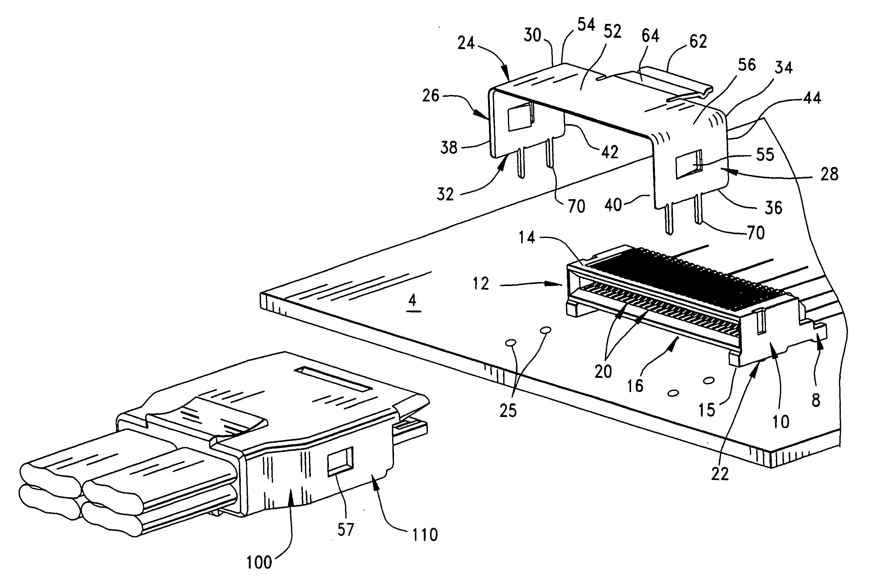
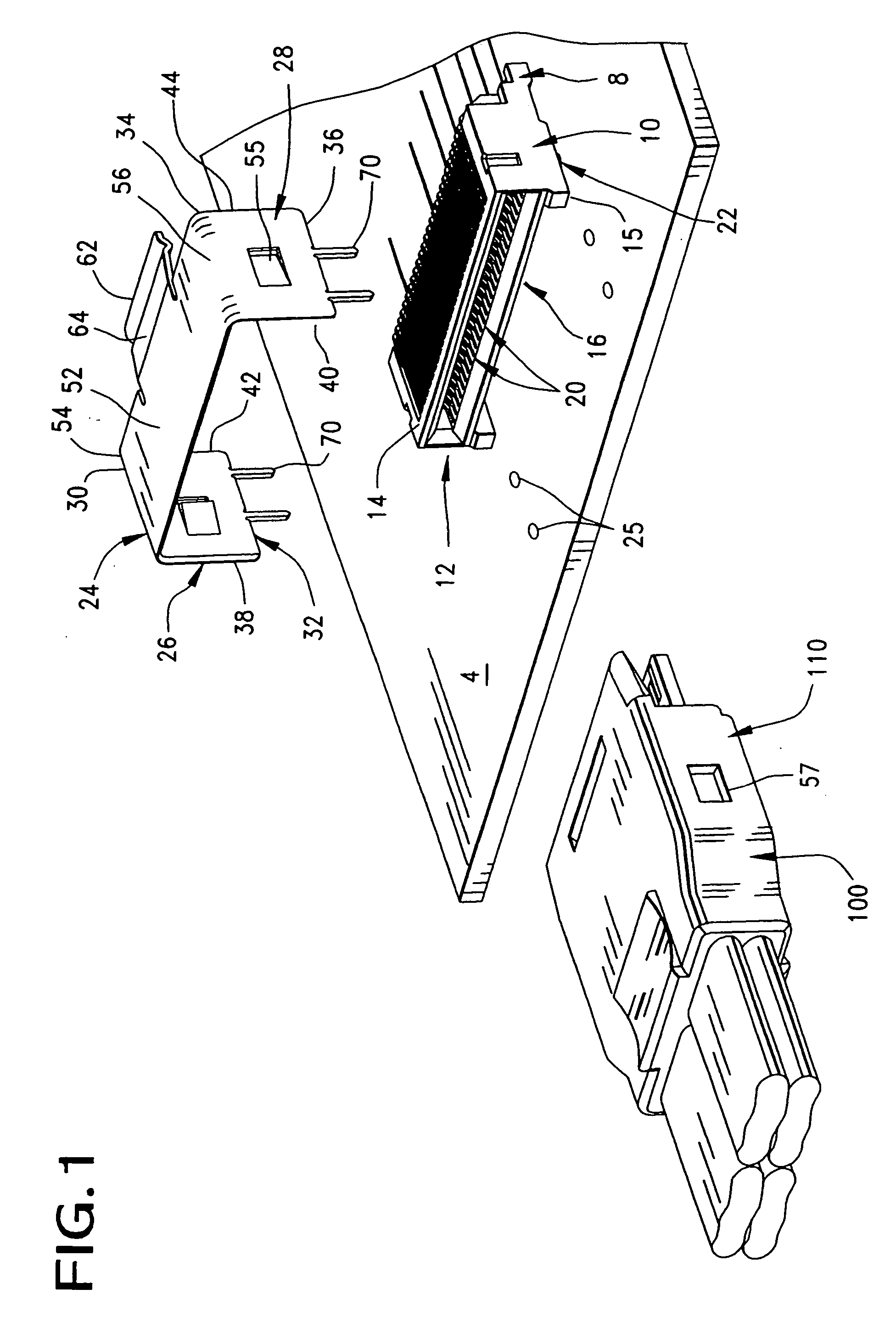
[0043]FIG. 1 illustrates an exploded view of an electronic assembly 2 used to exchange electrical signals between conductive traces 6 of a circuit board, or other substrate, 4 and electrical conductors in a cable 101. In FIG. 1, the electronic assembly 2 shown includes a circuit board 4 to which electronic components such as integrated circuits, resistors, capacitors inductors and the like can be mounted. As is well-known, electronic components mounted to circuit boards are interconnected by one or more electrically conductive traces 6, at least some of which are located on at least a surface of the substrate 4. Electrical signals may be transmitted through the conductive traces 6 by way of a receptacle connector 8 that is mounted to the substrate 4 and which mates with an opposing cable connector.

[0044]FIG. 1 shows the receptacle connector 8 attached to the circuit board 4 using either mounting posts, screws or soldered into place as shown, all of which are well-known in the art. ...


PUM


Abstract

A plug connector is disclosed that has a body portion and a circuit card extending forwardly of a mating face of the connector. The circuit card is protected in place by a pair of protective flanges that extend forwardly from the body portion and which flank the circuit card to protect it from stubbing and to provide a first means for aligning the plug connector with the receptacle connector. One or more projections formed on the exterior of the plug connector provide second means for aligning the plug connector with the receptacle connector.

Description

REFERENCE TO RELATED APPLICATIONS [0001] This application claims priority of prior U.S. Provisional Patent Application Nos. 60,637,013, filed Dec. 17, 2004, 60 / 655,673, filed Feb. 23, 2005 and 60 / 704,698, filed Aug. 2, 2005. BACKGROUND OF THE INVENTION [0002] The present invention relates generally to cable connectors, and more particularly to cable connector that mate with circuit board connectors that have a structure which eliminates the need for a shielding cage or guide frame to be utilized with a mating circuit board connector. [0003] It is a common practice in the electronic arts to connect cables to a circuit board by terminating the cables to a connector, typically a plug connector, and then mating the connector to a receptacle connector that is mounted on a circuit board. A well-known problem with connecting cables to circuit board-mounted connectors is the tendency for the cable's weight and movement to loosen the points of attachment of the receptacle connector to the ci...

Claims


Application Information

Patent Timeline
Patent Type & Authority Applications(United States)
IPC IPC(8): H01R24/00H01R12/71
CPCH01R13/6272H01R12/7005H01R12/7023H01R12/707H01R12/727H01R13/6581
Inventor DAWIEDCZYK, DANIEL L.HARWATH, FRANK A.NEER, JAY H.BRINKERHOFF, CLEAVERHALL, THOMASLANG, HAROLD KEITHSWENSON, JENNIFERBANAKIS, EMANUEL G.REGNIER, KENT E.
Owner MOLEX INC
Why Eureka
Try Eureka