Inverted flange flex boot

a flex boot and flange technology, applied in the direction of sleeves/socket joints, pipe joints, mechanical equipment, etc., can solve the problems of lack of a means to mount such a protective guard in the current conventional sealing boots, and the need for a protective shield or guard in the conduit, etc., to overcome the drawbacks and shortcomings

Inactive Publication Date: 2006-07-27
HENRY DREW P
View PDF21 Cites 9 Cited by
  • Summary
  • Abstract
  • Description
  • Claims
  • Application Information

AI Technical Summary

Benefits of technology

[0006] It is the object of the present invention to overcome the drawbacks and shortcomings of conventional sealing devices. This present invention allows a sealing boot to be installed on a flange mounted on a side of a tank or wall through which a conduit penetrates and allows access to the sealing boot from an opposite side. The sealing boot of the present invention has two sealing members, a first sealing member for the flange and a second inverted sealing member for the conduit, such that the second sealing member is directed towards the conduit opening and may penetrate the tank. Additionally, the present invention provides for the securing of other protective devices used in covering underground plumbing.

Problems solved by technology

Another deficiency with conventional sealing devices is that in applications with underground conduits, the conduit requires a protective shield or guard.
Current conventional sealing boots lack a mean to mount such a protective guard.

Method used


Image

  • Inverted flange flex boot
  • Inverted flange flex boot
  • Inverted flange flex boot

Examples


Embodiment Construction

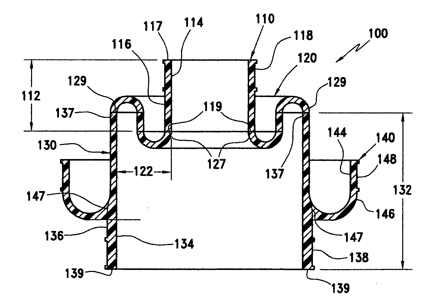
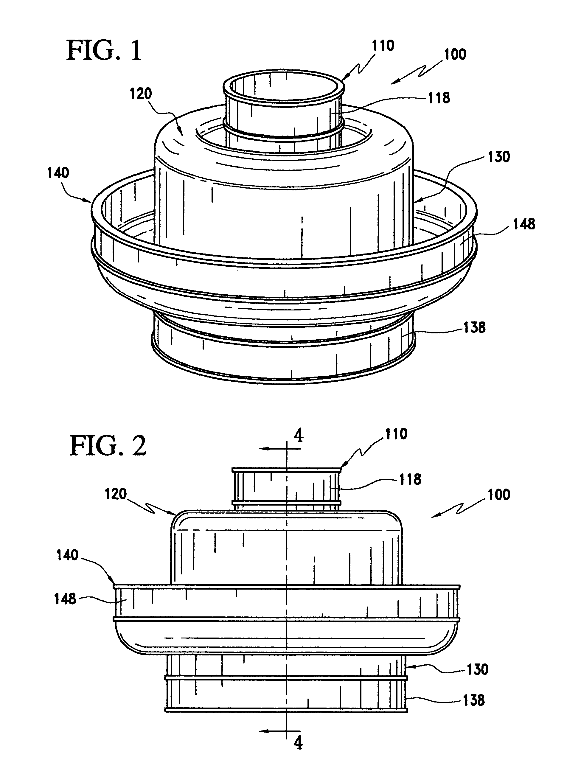
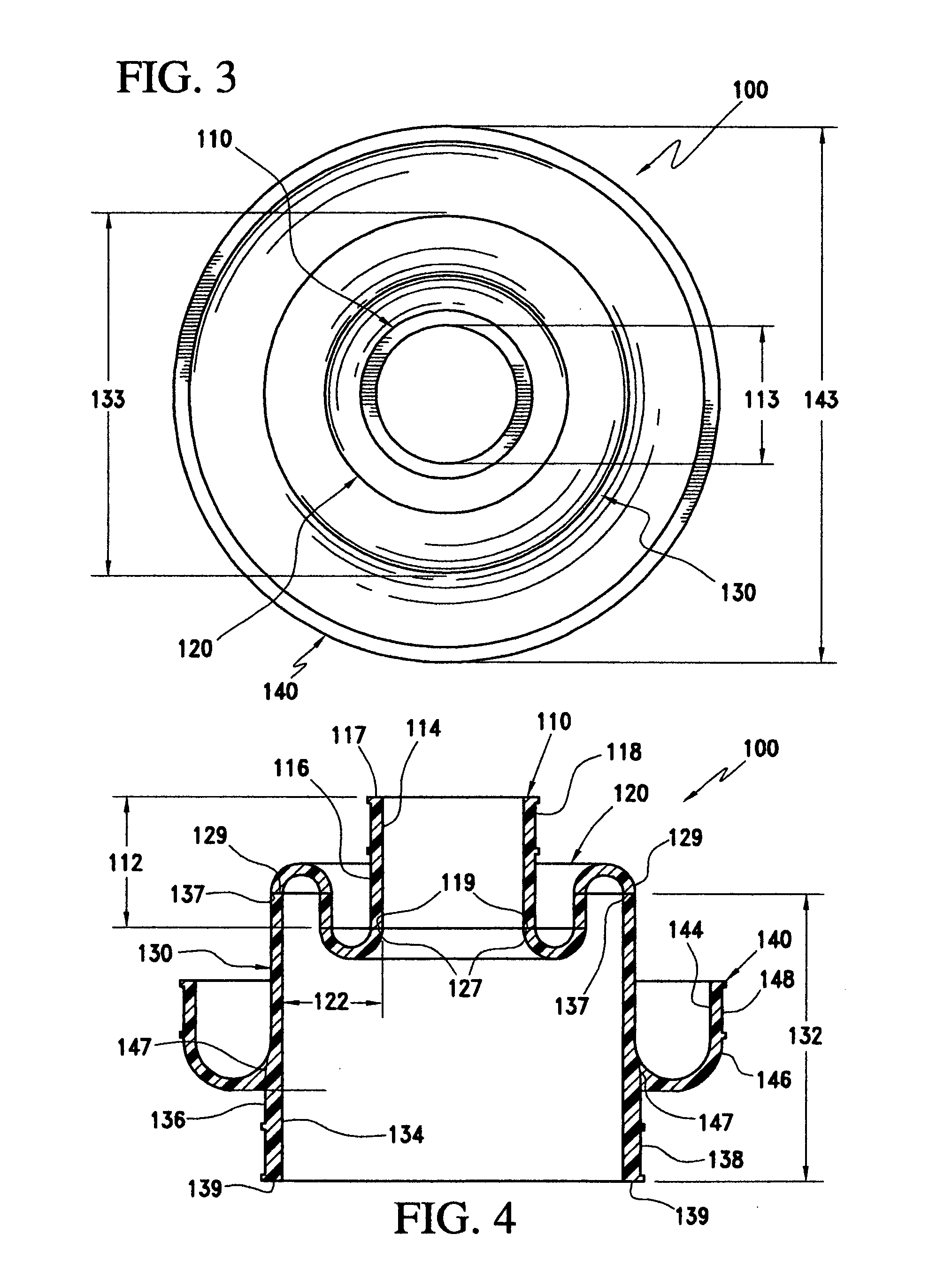
[0022]FIGS. 1 through 5 show a quick fitting flexible boot device 100, made in accordance with this invention. The device 100 is designed to be operably configured to provide a seal for flanges installed on tanks, walls, etc. in an underground environment.

[0023] The device 100 is preferably fabricated as a one-piece construction. The device 100 includes three annular portions, 110, 130 and 140 and a connecting portion 120 as shown in FIGS. 1 through 5. The device 100 is operably configured to fit over a mounting flange 30, common to the art as shown in FIG. 5 installed on a tank or wall 15, so as to cover the mounting flange 30 and provide a seal to the mounting flange 30 and seal a conduit 20 which penetrates the flange 30. The device 100 can be use internally or externally to the tank 15. It should be appreciated that mounting flange 30 can be any known or later developed mounting flange for attaching to tanks or walls.

[0024] The device 100 is preferable constructed out of a sin...


PUM


Abstract

The present invention discloses a sealing device for sealing a pipe passing through a wall. The device includes a first member and second member. The first member is substantially flexible, has an exterior surface and two axially aligned and opposed orifices, wherein the first orifice has a diameter less than the second orifice. The second member is disposed annularly on the exterior surface of the first member and the second member is operably configured to engage a first side of the wall when the sealing device is in use. The first orifice is operably configured to sealably engage a conduit such that the first orifice is accessible from a second opposing side of the wall when the sealing device is in use.

Description

CROSS REFERENCE TO RELATED APPLICATION [0001] This application is a nonprovisional application of U.S. Application No. 60 / 647,912, filed on Jan. 27, 2005, which is incorporated, in its entirety, herein by reference.BACKGROUND OF THE INVENTION [0002] 1. Field of Invention [0003] This present invention relates to sealing devices for tubes that extend through walls and the mounting devices thereof. [0004] 2. Description of Related Art [0005] Numerous conventional sealing devices exist that provide a means for sealing a conduit that extends through a wall or a tank. Additionally, in the underground tank environment many times an internal and external seal are required. SUMMARY OF INVENTION [0006] It is the object of the present invention to overcome the drawbacks and shortcomings of conventional sealing devices. This present invention allows a sealing boot to be installed on a flange mounted on a side of a tank or wall through which a conduit penetrates and allows access to the sealing ...

Claims


Application Information

Patent Timeline
Patent Type & Authority Applications(United States)
IPC IPC(8): F16L21/025
CPCF16L5/10
Inventor HENRY, DREW P.
Owner HENRY DREW P
Why Eureka
Try Eureka